Wavelet-Based Highpass Filtering
The complementary operation to wavelet-based lowpass filtering is wavelet-based highpass filtering, a process analogous to highpass filtering in the frequency domain. To create a wavelet-based highpass filter, the wavelet coefficients of the lowest detail level, that is, the lowpass output of the last subband stage (the Xk), need to be attenuated. Although this process is rarely found in image processing, it is conceptually easy to implement.
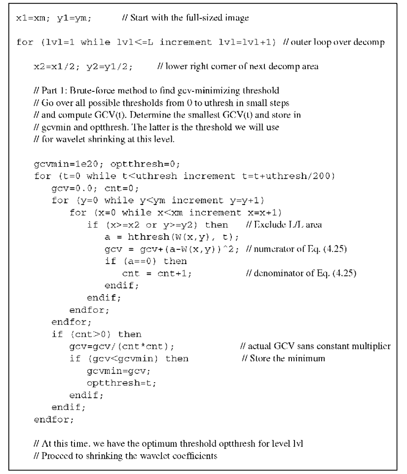
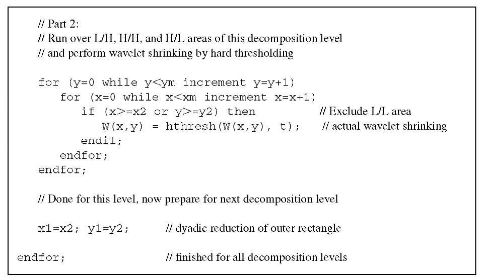
Algorithm 4.6 GCV-based denoising. Pseudocode to perform wavelet shrinking with a separate threshold per decomposition level determined through minimization of GCV. The algorithm expects a wavelet-transformed input image W(x,y) with multiple levels of decomposition, arranged as shown in Figure 4.8. The size of W(x,y) is xm and ym, both powers of 2. The number of decomposition levels is L. This algorithm relies on a function hthresh for hard thresholding. Wavelet coefficient shrinking takes place in W(x,y), and upon termination of this algorithm, W may be subjected to the inverse wavelet transform to restore the denoised image.
Algorithm 4.6 GCV-based denoising (continued). This part performs the actual wavelet shrinking.
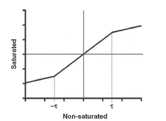
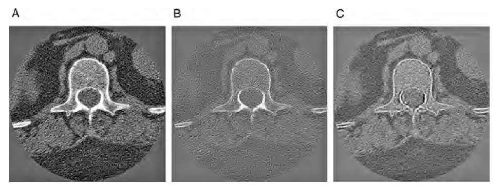
Setting the L/L coefficients of the lowest detail decomposition to zero, or shrinking them strongly, effectively removes background trends, but it also causes block artifacts upon reconstruction. In analogy to the threshold functions shown in Figure4.10, a soft attenuation of the lowpass coefficients \k can be achieved with a saturation function (Figure 4.15) that attenuates the lowpass coefficients \k if they exceed a certain threshold t . Such a saturation function can be described as where k is the attenuation factor for high-valued coefficients. The sharpening operation involves three steps: wavelet decomposition of the original image, application of the saturation function to the L/L coefficients of the lowest decomposition level, and wavelet reconstruction. The result is comparable to a sharpening operation (see Section 2.3), but it does not amplify additive noise on the pixel level. This effect can be explained with the frequency response of the filters. The sharpening operation is based on the Laplacian filter, which emphasizes frequency components proportional to the square of their spatial frequency. Therefore, noise on the pixel level is most strongly amplified. Conversely, wavelet sharpening can be seen as wavelet shrinking at the lowest frequency level. As a consequence, no noise amplification takes place. An example is shown in Figure 4.16, where the saturation operation has been applied to the L/L region of a three-level decomposition with the Daubechies-12 wavelet.
FIGURE 4.15 Saturation function to attenuate high-level lowpass subband coefficients.
FIGURE 4.16 Comparison of convolution-based and wavelet-based sharpening. Image A is a cross-sectional CT image of a lumbar vertebra. Convolution-based sharpening (B) enhances the texture of the image, but it also strongly amplifies noise on the pixel level. With wavelet-based sharpening (C), perceived sharpness (texture enhancement) is comparable to convolution-based sharpening, but pixel noise (additive Gaussian noise) is not amplified.
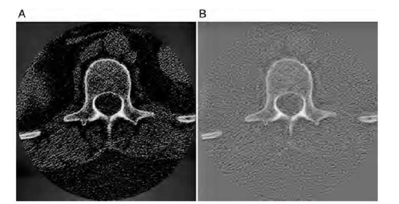
In a similar manner, very effective removal of background inhomogeneities is possible (background flattening). The conventional method is unsharp masking, that is, the subtraction of a strongly blurred version of the image from the original image. Depending on the window size, unsharp masking is affected adversely by strong edges. If the same operation, unsharp masking, is performed on the L/L region of the lowest decomposition level, image detail is not affected. The wavelet-based unsharp masking operation therefore involves three steps: wavelet decomposition of the original image, application of an unsharp masking operation to the L/L coefficients of the lowest decomposition level, and wavelet reconstruction. The result of this operation is shown in Figure 4.17. For this filter, the image was decomposed over three levels with the Daubechies-12 wavelet. Unsharp masking was performed on the lowest level, a square of 64 x 64 pixels in size, with a 32-pixel circular mask. Wavelet-based filtering removes the inhomogeneous background more effectively, while the background texture is retained and no burned-out regions appear.
FIGURE 4.17 Comparison of conventional unsharp masking and unsharp masking on the lowest level of wavelet decomposition. The original image is the CT cross section in Figure 4.16. Image A shows the result of unsharp masking, and image B shows the result of a wavelet-based operation, where only the lowest decomposition level was subjected to unsharp masking. Both images were subjected to gamma contrast enhancement to make the background texture more visible. Conventional unsharp masking shows loss of texture detail and large burned-out regions, whereas wavelet-based background removal shows a much more detailed texture.
![tmp2F-237_thumb[2] tmp2F-237_thumb[2]](http://what-when-how.com/wp-content/uploads/2011/06/tmp2F237_thumb2_thumb.jpg)
