27.5.
Vehicle Steady State Directional Stability
27.5.1.
Cornering Properties to Tyres Cornering Force and Slip Angle
When the wheels are in motion tyres are subjected to vertical as well as side (lateral) forces due to road camber, side winds, weight transfer and centrifugal force caused while negotiating a curved paths and steering the vehicle on turns. When a lateral force acts on a road wheel and tyre, a reaction that is a resisting force acts, between the tyres tread contact patch and road surface and opposes any sideway motion. This opposing resisting force is known as the cornering force (Fig. 27.33), whose magnitude is equal to that of lateral force. The increase

Fig. 27.33. Tyre trade contact patch distortion when subjected to side force.
in this cornering force is roughly proportion to the increase in lateral force until the tyre looses grip with the ground. Beyond this point the proportionality does not hold good with further
increase in lateral force so that tyre breakaway is likely to occur. However, the greater the cornering force generated between tyre and ground, the greater the tyre’s grip on the road.
When the lateral force pushes the supple tyre walls sideways, the resisting force causes the tyre contact patch to take up a curved distorted shape. Consequently the rigid wheel points and rolls in the direction it is steered, whereas the tyre region in contact with the ground follows the track continuously laid down by the deformed tread path of the contact patch (Fig. 27.33A). The angle made between the direction of the wheel plane and the direction in which it actually travels is known as the slip angle. With a small slip angle, each element of tyre remains in contact with the ground without slippage.

Fig. 27.34. Effect of slip angle on cornering force.
The amount of cornering force developed between the tyre and road depends on the following factors.
Slip Angle.
The cornering force increases linearly with increase of slip angle, up to about four degrees beyond which the cornering force increases non-linearly and at a much reduced rate (Fig. 27.34), depending to a large extent on tyre design.
Vertical Tyre Load.
As the vertical or radial load on the tyre increases for a give slip angle, the cornering force rises very modestly for small slip angles but at a far greater rate with larger slip angles (Fig. 27.35).
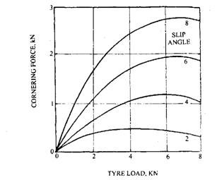
Fig. 27.35. Effect of tyre vertical load on cornering.
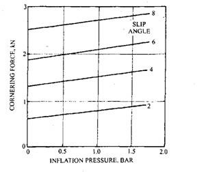
Fig. 27.36. Effect of tyre inflation pressure on cornering.
Tyre Inflation Pressure.
For a given slip angle, the cornering force (Fig. 27.36) rises linearly with the increase of tyre inflation pressure as well as with the increase of the tyre inflation slip angle.
Cornering Stiffness or Cornering Power.
The centrifugal force (lateral force), developed due to movement of a vehicle on a curved path, pushes each wheel sideways against the opposing ground reaction of tyre contact patch. Consequently, the tyre casing and tread deform very slightly into a semicircle in the region of the contact patch. As a result the path followed by the tyre at ground level is not exactly the same as the direction pointing of the wheel. The resistance offered by the tyre crown or belted tread region of the casing preventing it from deforming and generating”a slip angle is a measure of the tyre’s cornering power. The cornering stiffness is defined as the cornering force developed for every degree of slip angle generated.
![]()
The cornering stiffness of a tyre is the slope of the cornering force vs slip curve usually along its linear region (Fig. 27.34). The larger the cornering force developed per degree of slip angle, the greater is the cornering stiffness of the tyre and the smaller is the steering angle correction to sustain the intended path of the vehicle.
Self-aligning Torque.
If a stationary wheel is loaded, the contact patch is spread about the geometric centre of the tyre at ground level. When the loaded wheel rolls forward, the casing that supports the tread is deformed and pushed slightly to the rear (Fig. 27.37). As a result the larger amount of the cornering force generated between the ground and each element of tread shifts from the static centre of pressure to some dynamic centre of pressure, which is located behind the vertical centre of the tyre. The amount of shift, however, depends on the wheel construction, load, speed and traction. The majority of the area of tread to ground reaction is concentrated behind the static centre of the wheel. The actual distribution of cornering force is shown by the shaded area between the centre line of the tyre and the cornering force plotted line (Fig. 27.37). The total cornering force is approximately proportional to this shaded area and its resultant dynamic position is known as the centre of pressure. The distance between the static and dynamic centres of pressure is known as the pneumatic trail (Fig. 27.37). The magnitude of pneumatic trail depends upon the degree of creep between tyre and ground, the vertical wheel load, tyre inflation pressure, vehicle speed, and tyre construction. The longer contact patch generally provides a greater pneumatic trail. The radial ply tyres have longer contact patch than the cross-ply construction.
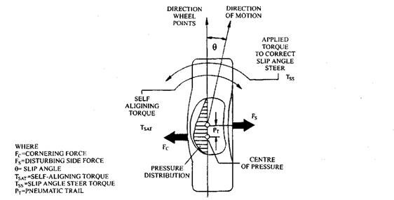
Fig. 27.37. Illustration of self-aligning torque.
As explained above if a moving vehicle is steered on a turn in the road, the lateral (side) force, Fs, gives rise to an equal and opposite reaction force at ground level called the cornering force, Fc. The cornering force centre of pressure is to the rear of the geometric centre of the wheel and the side force acts perpendicularly through the centre of the wheel hub. Because of the offset between these two forces, known as the pneumatic trail, tp, a couple is produced about the geometric wheel centre, which tends to turn both steering wheels towards the straight ahead position. This self-generating torque, which endeavours to restore the plane of the wheels with the direction of motion, is known as the self- aligning torque (Fig. 27.37). The characteristic of the tyre causes the steered tyres to return to the original position after negotiating a bend in the road. The self-aligning torque, Tsat may be defined as the product of the cornering force, Fc and the pneumatic trail, tp.
Thus, Tsat = Fcx tp, Nm.
The increasing in deflection of tyre due to high load enlarges the contact patch. The pneumatic trail extends and hence the self-aligning torque increases with the increase of the contact patch-area. On the other hand increasing the inflation pressure for a given tyre load shortens the pneumatic trail and reduces the self-aligning torque. The load transfer during braking, accelerating and cornering also influences self-aligning torque because this alters the contacts patch area. The self-aligning torque is little affected with small slip angles during braking or accelerating, but with larger slip angles braking decreases the aligning torque and acceleration in-
creases it (Fig. 27.38). The static steering torque, i.e. the torque needed to rotate the steering when the wheels are not rolling, is higher than and is independent of the generated self-aligning torque when the vehicle is moving. The high static steering torque is due to the distortion of the tyre casing and the friction created between the tyre tread elements at ground level.
27.5.2.
Directional Stability
Neutral Steer.
Consider the situation of a vehicle moving forward along a straight path. Let a side force due possibly to a gust of wind acts thought the vehicle’s centre of gravity and for simplicity it is assumed to be acting in the mid-way between the front and rear axles. If an equal steady state slip angles are produced due to side forces on the front and rear tyres, the vehicle moves on a new straight line path at an angle in proportion to the generated slip angles (Fig. 27.39). This motion is free of a yaw velocity which is caused due to a rotation about a vertical axis passing
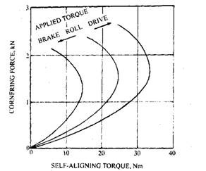
Fig. 27.38. Variation of self-aligning torque with cornering force.
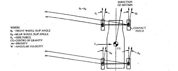
Fig. 27.39. Neutral steer on straight track.
through the centre of gravity, and hence is known as neutral steer. In this situation projection lines, drawn perpendicular to the tyre tread direction of motion, never meet without having any rotational turn of the vehicle.
Over-steer.
Consider the situation of a vehicle moving forward in a straight path, a disturbing side force acts through the vehicle centre of gravity and the mean steady static sleep angles of the rear wheels are greater than at the front. This may be possible due to the suspension design, tyre construction and inflation pressure or weight distribution. The directional path of the vehicle, in this case, is a curve towards the direction of the applied side force (Fig. 27.40A). To understand this directional instability, projection lines are drawn perpendicular to the direction of the treads of the tyre’s roll. These projection lines roughly intersect each other at some common point, the instantaneous centre. As a result a centrifugal force is produced that acts in the same direction as the imposed side force. In affect, the whole vehicle tries to rotate about this centre tending to swing towards the disturbing force. This condition is known as over steer. To correct this situation the vehicle has to be the steered in the same direction as the side force away from the centre of rotation.
Now consider that a vehicle is turning a corner when the slip angles of the rear wheel tyres are also greater than on the front tyres (Fig. 28.40B). In this condition all the projected lines, drawn perpendicular to the direction of motion of each tyre corresponding to its slip angle, merge together at some common point called dynamic instantaneous centre. This common point is
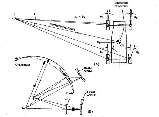
Fig. 27.40. Over-steer. A. On straight track. B. On turns.
forward of the rear axle and further in. Therefore a shorter radius of turn is produced than that for the Ackermann instantaneous centre for a given steering wheel angle of turn. Under these driving conditions the vehicle tends to steer towards the bend. Since the radius of the turn is reduced, the magnitude of the centrifugal force acting through the vehicle centre of gravity becomes larger so that the over steer tendency of the vehicle is raised. This over steer response increases further at higher vehicle speeds on a given circular path, because the rise in centrifugal force produces more tyre to ground reaction so that the slip angles at each wheel is correspondingly increased. The over steering situation causes an unstable driving condition because the vehicle tends to turn more sharply into the bend with the rise of speed unless the lock is reduced by the driver. A rear wheel drive vehicle has a greater tendency for over steer, as the application of tractive effort during a turn reduces the cornering stiffness and increases the slip angles of the rear wheels. Under-steer.
Consider a vehicle initially moving along a straight path is imposed by a disturbing side force through the centre of gravity and the slip angle on the front tyres is larger than at the rear
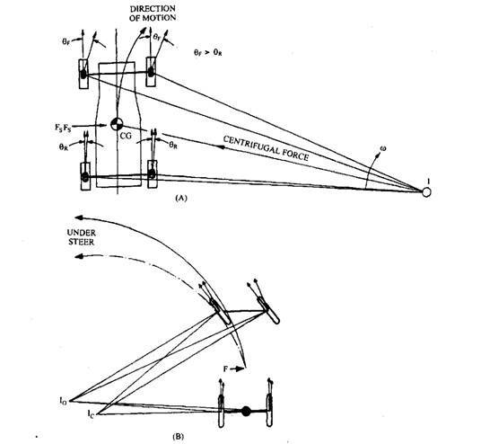
Fig. 27.41. Under-steer. A. On straight track. B. On turns.
(Fig. 27.41A). In this case, the lines of projection perpendicular to the tyre tread direction of motion meet approximately at a common point on the opposite side to that of the side force. The vehicle’s directional path is a curve away from the applied side force. This gives rise to a centrifugal force which acts in opposite direction to the disturbing side force. Consequently the vehicle rotates about the instantaneous centre and moves in the same direction as the disturbing force. This steering condition is known as under-’ steer. This can be corrected by turning the steering in the opposite direction to the disturbing force away from the instantaneous centre of rotation.
When the vehicle is turning a bend, if the slip angles generated on the front wheel tyres are larger than those on the rear tyre (Fig. 27.4 IB), all the projection lines drawn perpendicular to the direction of motion of each tyre, intersect approximately at one point forward of the rear axle. The radius of turn, in this case, is greater than that achieved with the Ackermann instantaneous centre. With the larger slip angles generated on the front wheels the vehicle tends to steer away from the bend. Because the radius of turn is larger, the magnitude of the centrifugal force produced at the centre of gravity of the vehicle is less than for the over-steer condition. The under-steer tendency, therefore, is generally less severe and can be corrected by turning the steering wheels more towards the bend. When a front wheel drive vehicle negotiates a curved path, the cornering stiffness of the front tyres is reduced so that if tractive effort is applied the slip angles are increased at the front causing an under-steer condition.
Figure. 27.42 presents a comparison between the steered angle of the front wheels and vehicle speed for various steering tendencies. The neutral steer maintains a constant steering angle throughout the entire speed range, whereas both under and over-steer tendencies increase with speed. The under-steer is relatively progressive as the speed rises but over-steer increases rapidly with speed. It is generally accepted that an over-steer condition is dangerous and undesirable. Therefore the slip angles generated on the front wheels should be slightly larger than at the rear to produce a small under-steer tendency.
