1.9. Vehicle Assemblies
The main components of an automobile can be sub-grouped in the following assemblies
(Chart 1.2)
(i) Engine or power plant
(») Running gear or basic structure
(Hi) Driving system
(iv) Basic Control system
(v) Electrical system
(ui) Accessories
Engine. The prime movers used in almost all vehicles are either gasoline (petrol) or diesel
engines. Some speciality automobiles use a different type of engine. The diesel engine consumes
considerably less fuel than the gasoline engine, when operated at low speeds. The rotating
combustion chamber engine is gaining popularity in small cars, and its use will probably
increase. Turbine engines show promise, especially in commercial vehicles. They are powerful,
light weight and produce less hydrocarbons and carbon monoxides. They are ideally suited to
replace diesel engines in over-the-road load carrying vehicles. Battery or electric vehicles are
also being introduced to conserve fossil fuels and to minimise pollution.
The engine is located either in the front, mid-ship or rear. Front mounted engines are more
common in automobiles. The engine contains mechanical parts, fuel system, cooling system,
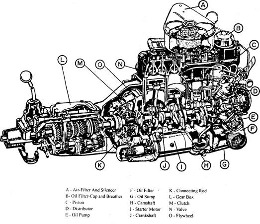
lubricating system and exhaust system. Figure 1.21 shows an automobile engine with its clutch
and gearbox. The radiator is located at the front of the engine.
Thinning Gear. The running gear comprises of the frame, suspension, springs, shock
absorbers, wheels, rims and tyres. The tyres are the only place where the automobile touches
the road. All of the engine power, steering and braking forces must operate through these tyre-to
road contact areas. Control of the vehicle is reduced or lost when the tyre does not contact the
road or when skidding begins.
The suspension keeps the tyre in contact with the road as much as possible in all road
conditions. The suspension system must be strong enough to resist axle twisting from high
engine power and from brake reaction. The suspension system consists of springs, shock
absorbers and linkages or arms.
Fig. 1.21. An automobile engine with clutch and gearbox.
The frame is a rigid structure that forms a skeleton to hold all the major units together. The
wheels and tyre assemblies support the frame and the units are attached to it, through front
and rear suspension systems so as to follow the road irregularities.
Driving System. The driving system comprises of the clutch, transmission, driveline,
differential and rear axle. The driving system carries power to the driving wheels from the
engine. A clutch or torque converter is connected to the engine crankshaft to effectively
disconnect or connect the engine with the driveline. *
The function of the transmission is to provide gear reduction, which produces high torque
to start the automobile from rest and drive it up the steep grades. It also provides a reverse gear
for backing the automobile. A propeller shaft is required to transmit the engine power to the
rear axle. It has universal joints on each end to provide flexibility as the suspension position
changes. A differential incorporated with a rear axle, splits the incoming power to each drive
wheel. This also allows the drive wheels to turn at different speeds as they go over bumps and
round corners.
Control System. The steering and braking systems form the basic control system. The
steering gear controls the direction in which the front wheels are pointed. The steering systems
have some parts (i.e. the steering gear) bolted to the frame, some parts (i.e. the steering column)
bolted to the body and some parts closely integrated with the front suspension system.
The brake system slows down the speed of the vehicle or stops it at the driver’s will. The
entire brake system is located in the chassis. The brakes are mounted inside the wheels. The
brake designs are either drum type or disc type. Four-wheel disc brakes are more common in
use.
Electrical System. The electrical system is a part of both chassis and body. The system
includes the starting, charging, ignition, lighting and horn circuit. Some electrical circuits are
for engine operation, some for power transmission and others for lighting and operation of
protective devices and accessories.
Accessories. Accessories are used to make driving more pleasant. They include car heater,
air-conditioner, radio, windscreen wiper, indicators etc.
1.9.1. Engine Position
Front Engine. There are a number of reasons for locating the engine at the front of a car
as shown in Fig. 1.22. The large mass of an engine at the front of the car provides the driver
protection in the event of a head-on collision, and engine-cooling system becomes simpler.
Also the cornering ability of a vehicle becomes better due to concentration of weight at the front.
Fig. 1.22. Front-engined car.
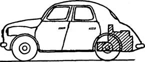
Rear Engine. With the engines mounted at
the rear of the vehicle the components like the
clutch, gearbox and final drive assembly can be
installed as a single unit. This arrangement re-
quires the use of some form of independent rear
suspension. Rear-engine layout is mostly con-
fined to small cars, as this adversely effects on the
“handling* of the car. Also it takes up a larger
space in comparison to the front-engined car for
carrying luggage. However, a rear-engined layout
increases the load on the rear driving wheels, providing better grip on the road. Figure 1.23
presents one of the rear-engined cars. The front seats are close to the front wheels than a
front-engined car, and the floor is quite flat.
Central and Mid-engine. This engine location is generally confined to sports cars because
this provides both good handling and maximum traction from the driving wheels. This arran-
gement, however, is not convenient for everyday cars as the engine takes up space that is
Fig. 1.23. Rear-engined car.
normally occupied by passengers. The mid-
engine layout, shown in Fig. 1.24, combines
the engine and transmission components in
one unit.
1.9.2. Drive Arrangements
Rear-wheel Drive. In this layout (Fig.
1.25) the rear wheels act as the driving
wheels and the front wheels swivel for steer- .
ing of the vehicle. The location of the main
components in this arrangement makes each unit accessible. A major drawback is the protrusion
of the transmission components into the passenger compartment due to which a larger bulge is
produced in the region of the gearbox and a raised long tunnel down to the centre of the car floor
is formed to accommodate the propeller shaft.
In this driving arragement, the load transfer takes place from the front to rear of the vehicle
during hill climbing or acceleration providing good traction. However, if the wheels lose
adhesion, the driving wheels move the rear of the car sideways causing the car to ‘snake’.
Front-wheel Drive. This layout (Fig. 1.26) is compact as the engine is mounted transver-
sely and hence very popular for use on cars. From space considerations the length of the engine
is the critical, but the use of V-type engines for larger power units has enabled to place the
engine transversely. Consequently, the placement of all the main components under the bonnet
(hood), and the removal of floor bulges and tunnel provide maximum space for the rear
passengers. Transverse mounting of the engine also simplifies the transmission. The use of
bevel-type final drive is eliminated; instead a simple reduction gear along with a differential
transmits the power through short drive shafts to the road wheels. Each drive shaft is fitted
with an inner and outer universal joint. The outer joint accommodates the steering action and
is specially designed to transmit the drive through a large angle. When the front wheels are
used for steering, the driving force acts in the same direction as the wheel is pointing. Also the
Fig. 1.24. Mid-engined car
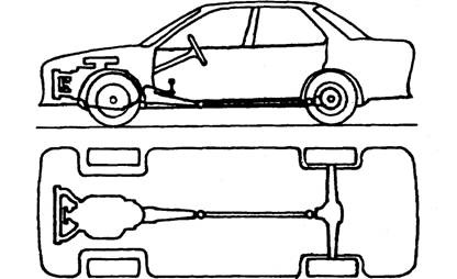
Fig. 1.25. Rear-wheel drive.
vehicle is being ‘dragged’ behind the front driving wheels. These features improve vehicle
handling especially in slippery conditions.
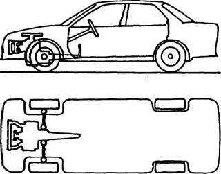
Fig. 1.26. Front-wheel drive.
Mounting the main units in one-assembly some-times makes it difficult to gain access to
some parts, but this problem has largely been overcome now a days. One disadvantage is that
the driving wheels have fewer grips on the road when the vehicle is accelerating and negotiating
a gradient. This problem can be partly rectified by placing the engine well forward to increase
the load on the driving wheels, but the car is then liable to become ‘nose-heavy’ causing the
steering more arduous. In cases where the driver’s steering effort becomes excessive, the car is
often fitted with power-assisted steering.
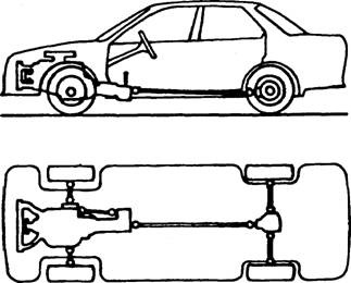
Fig. 1.27. Four-wheel drive.
Four-wheel Drive. This arrangement (Fig. 1.27) is safer because of distribution of the drive
to all four wheels. The sharing of the load between the four wheels during acceleration reduces
the risks of wheel spin specifically on slippery surfaces like snow and mud. In addition the
positive drive to each wheel during braking minimizes the possibility of wheel lock- up. On an
icy road or across off-highway a two-wheel-drive vehicle soon becomes non-drivable due to the
loss of grip of one of the driving wheels which causes the wheel to spin.


