14.8.
Alternators
14.8.1.
Principle of Operation
The principle of operation of the alternator is illustrated in Fig. 14.14. A single conductor loop passes through the pole-pieces of a soft-iron horseshoe-shaped yoke. Open ends of the loop form the leads for the external circuit (in this case connected to a light bulb). A permanent magnet pivots in between the pole-pieces and establishes a magnetic field (lines of flux) around the yoke. When the rotor shaft is driven by the fan belt drive, the permanent magnet rotates on its axis. During this rotation as the orientation of the magnet changes relative to the pole-pieces, the magnetic field in the yoke is continually in a state of growth and decay. As a result, the magnetic flux lines constantly cut through the two half-conductors of the loop. Whenever the two magnet poles are adjacent to the yoke poles the maximum flux lines cut through the two half-conductors due to which a flow of current is established in the conductor loop by the induced emf.

Fig. 14.14. Basic single-loop alternator.
In Fig. 14.14A the magnet rotates clockwise with its North Pole on the left-hand side and the South Pole on the right-hand side of the iron yoke. The lines of flux circulate round the yoke in a clockwise direction from the North to the South Pole. Also, the movement of the magnet causes the lines of flux to cut through the conductors and the induced voltage produces a flow of current in the conductor loop in a clockwise direction.
In Fig. 14.14B the magnet is now rotated a further half revolution so that the position of the magnet poles is reversed, with the North Pole being on the right-hand side of the yoke and the South Pole on the left-hand side. As a result, the direction of the lines of flux round the yoke is in an anticlockwise direction. This reverses the direction of flow of the generated current in an anticlockwise direction.
Thus due to the rotation of the magnet, the yoke poles continually change their north and south polarities. Consequently, the direction of the flux-path lines is constantly reversed so that the current in the conductors continuously changes from a maximum value in one direction to a maximum value in the opposite direction. A current with repeatedly changing of its direction of flow is termed as an alternating current (AC). With a two pole magnet the change of its
direction takes place once in every complete revolution of the magnet. The output produced by one complete revolution is called as an alternating-current cycle. 14.8.2. Construction
The alternators in practice use many conductor windings around a ring shaped yoke, known as the stator windings and the stator yoke (Fig. 14.15A). Also the rotor is made in two halves to reduce the voltage fluctuation further, and each half has several segment poles of like polarity so that when they are fitted together they form a ring of alternating North and South Poles (Fig. 14.15B).
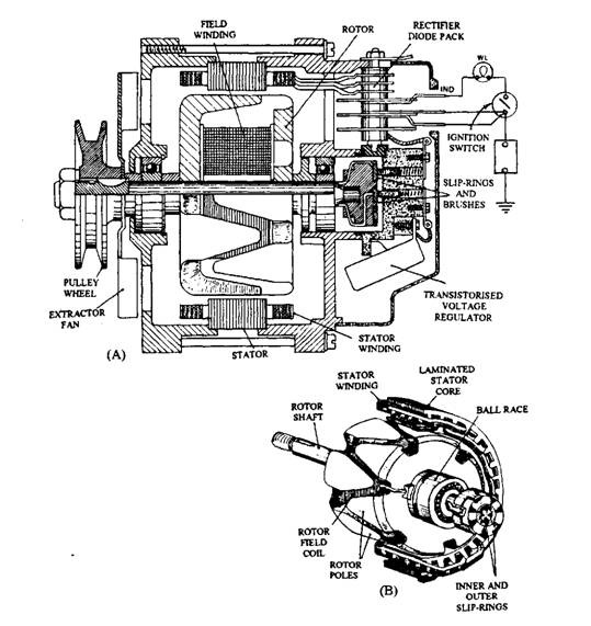
Fig. 14.15. Alternator. A. Section view. B. Pictorial view of rotor and stator.
An exploded view of a typical alternator (Lucas) is shown in Fig. 14.16. This alternator is a 3-phase, 12 pole machine having a rectifier and micro-electronic regulator. The casing of the alternator is made of lightweight aluminium alloy, and it contains :
(i) the rotor to form the magnetic poles,
(ii) the stator to carry the windings in which the current in generated, (Hi) the rectifier pack to convert AC and DC, and
(iv) the regulator to limit the output voltage.
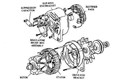
Fig. 14.16. Exploded view of alternator.
Rotor.
The rotor has a field winding, wound around an iron core and pressed on to a shaft. An iron claw is placed at each end of the core to form 12 magnetic poles. Each claw has 6 fingers to form separately North Poles and South Poles (Fig. 14.17).
The magnet excitation winding is wound around a soft-iron core. Two carbon brushes rub on two copper slip rings, and make contact with the windings. Two types of brush arrangement in use are ;
(a) Cylindrical or barrel type in which two slip rings are placed side-by-side.
(6) Face type in which the two brushes are fitted coaxially with the shaft.
The rotor is driven by the crankshaft through a vee-belt-pulley and Woodruff-type key. Since alternators are operated for speeds up to 15,000 rpm, and because the belt tension must be sufficient to prevent slip at this high speed, the rotor is supported on ball bearings. These bearings are lubricated and sealed for its life period. A centrifugal fan fitted adjacent to the pulley circulates air through the machine to cool the semiconductor devices used in the system and to prevent overheating of the windings.

Fig. 14.17. Rotor construction.
Stator. The stator is a laminated soft-iron member attached rigidly to the casing which carries three sets of stator windings (Fig. 14.18). The coils of comparatively heavy-gauge enamelled copper wire form the stator windings and are arranged so that separate AC waveforms are induced in each winding when cut by the changing magnetic flux. The two ways in which the three sets of windings can be interconnected are (i) Star and (ii) Delta.
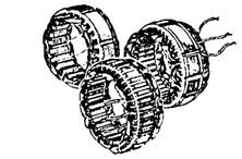
Fig. 14.18. Stator construction.
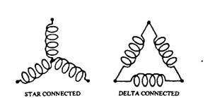
Fig. 14.19. Stator windings.
Both types of stator windings are shown in Fig. 14.19. In the Star arrangements, one end of the three windings is connected together and the output current is supplied from the ends A, B and C. In the Delta arrangement the three windings are connected in the form of the Greek letter ‘A’ and the output is again taken from points A, B and C.
The main difference between the two connections is in the magnitude of the output. In the Star arrangement the voltage between any two output points is the sum of the emf induced in two associated windings, whereas the voltage from the Delta arrangement is limited to the emf induced in a single winding only. For a given speed and flux density,
Voltage output from star winding = 1.732 x voltage output from Delta winding.
The output from the Star arrangement is obtained mainly from two windings, but the total is not doubled. It is because only one winding can be positioned at any one time at the point of maximum magnetic flux, hence the value 1.732 i.e. V3~. The energy generated for both arrangements at a given speed is equal, and hence a comparison of current outputs gives,
Current output from Delta winding = 1.732 x current output from Star winding.
The majority of the alternators for light-cars use the star windings, but the Delta wound stator is preferred for higher current output. On some special designs of heavy-duty alternators, the stator windings can be altered from Star to Delta when a large output current is needed.
14.8.3.
Current Rectification
For rectification of the generated current, some alternators install an external plate-type selenium rectifier, but most units use semiconductor diodes, arranged to form a bridge network. With a 3-phase output, 6 diodes are arranged as shown in Fig. 14.20 to give full wave rectification. Since the diodes act as one-way valve, the current generated in any winding always flows to the battery through the terminal B+. A complete circuit is required for the flow of this direct current, therefore an appropriate earth diode (the negative diode in this case) is used to pass current from ‘earth’ to the active winding.
In addition to current rectification, the diodes do not allow flow of current from the battery when the alternator output voltage is less than the battery voltage. Therefore the diodes eliminate the use of a cut-out as is necessary in a dynamo charging system. With the alternator
stationary, the connection to the alternator B+ is ‘live’. This must be remembered while demounting an alternator from the engine. The battery earth terminal should be disconnected prior to initiating work on the alternator.
Figure 14.21 illustrates various options adapted to mount the rectifier diodes. However, in all constructions the semiconductors must be kept cool, so it is common to mount the diodes on a heat sink made of an aluminium alloy block or plate.
14.8.4.
Field Excitation
Unlike the dynamo, insufficient residual magnetism is present in the magnetic poles to initiate the charging process, hence a battery initially excites (activates) the field magnets. Early alternators incorporated a field relay to connect the battery to the field when the ignition is switched-on. Presently a self-excited system with three field diodes is used to supply the rotor field with a portion of the current generated by the
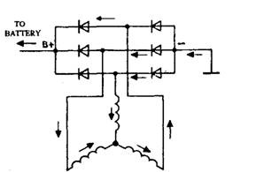
Fig. 14.20. Rectifier circuit.
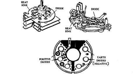
Fig. 14.21. Some common rectifier packs indicating diode location.
alternator (Fig. 14.22) when the alternator is charging. However the self-excited machine can not provide the initial current to energize the field to initiate the charging process, and hence a charge warning lamp is used to achieve this. The warning lamp sub-circuit supplies the initial field current and also provides a signal to warn the driver when the system stops functioning.
When the ignition is switched-on to start the engine, it connects the lamp to the battery making a circuit through the field to earth. The lamp is then illuminated and the field is excited to the extent controlled by the wattage of the lamp. A typical lamp size is 12 V, 2.2 W. With increase in the alternator speed, the p.d. on the output side of the field diodes also increases so that the voltage applied to the lamp gradually reduces. The light slowly fades and eventually goes out when the output voltage of the alternator equals the battery voltage (i.e. when the alternator cuts-in and starts to charge). At this stage, the field diodes provide total field current. The cutting-in speed, which is normally about 1000 rpm, depends on the field current. To have
an earlier cutting-in speed, the wattage of the lamp is required to be increased. From the above it is apparent that if the lamp is blown, the alternator fails to charge.
The rectifier and field diode arrangement used in a Lucas ACR type alternator is illustrated in Fig. 14.22. The cable from the charge indicator light is connected with the TND’ terminal on the alternator, which in turn is joined to the’+’ side of the field.
14.8.5.
Voltage Regulation
An alternator output voltage must be limited to prevent overcharging of the battery and to protect the electrical equipment against excessive voltage. Accurate voltage control is essential specifically with the ever increasing use of electronic system. Such control has also
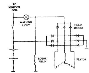
Fig. 14.22. Self excited field system-9 diodes.
allowed the use of sealed batteries as the possibility of overcharging is minimised.
Practically the voltage regulation is difficult to achieve on a vehicle alternator because the engine speed changes constantly. It is explained earlier that the output of an alternator without
regulation rises linearly with the engine speed. Alternator output is also directly proportional to magnetic field strength and in turn is directly proportional to the field current. The regulator controls this field current in response to alternator output voltage. Figure 14.23 illustrates a flow chart to represent the action of the regulator, showing how the field current is switched-off as output voltage increases and switched-on again as output voltage falls. The sudden switching of the field current does not cause abrupt changes in output voltage due to the very high inductance of the field (rotor) windings. The whole switching process takes only a few milliseconds. Many regulators also incorporate some temperature compensation device to have a higher charge rate in colder conditions and to reduce the rate in hot conditions.
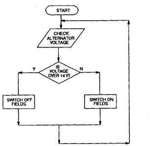
Fig. 14.23. Flow chart to represent the action of the regulator.
While examining regulator circuits it is necessary to know where the field circuit is interrupted. It is because some alternator circuits provide constant feed to the field windings from the excitation diodes, and the regulator switches the earth side. In other systems one side of the field windings is constantly earthed and the regulator switches the supply side. These two methods are represented in Fig. 14.24.
When output voltage is regulated, the voltage supplied to the field windings cannot exceed the pre-set level. This is turn allows only a small current to flow due to the resistance of the windings so that a limit is set for the field strength. This then limits the maximum current the alternator can produce.
Regulators can be mechanical or electronic, the latter being almost common on modern cars. The mechanical regulator has a winding connected across the output of the alternator. The magnetism produced in this winding is proportional to output voltage. A set of normally closed contacts is fixed to an armature, and is held in position by spring. The supply to the field windings is through these contacts. When the output voltage exceeds a pre-set
value, say 14.2 V, the magnetism in the regulator winding overcomes spring tension so that the contacts re-open. This switches off the field current and causes alternator output to fall. As output voltage falls below a pre-set value the spring closes the regulator contacts again. This process continues again and again. Figure 14.25 illustrates a simplified circuit of a mechanical regulator. This principle is almost same as very early voltage control of dynamo output.
Mechanical regulators suffer from the problem of wear on the contacts and other moving parts. Electronic regulators do not face this problem and with more accurate tolerance and much faster switching are far superior, producing a more stable output then mechanical regulators. They are also compact and vibration resistant. Because of the many advantages the electronic regulator are now fitted almost universally on alternators, reducing the number of connecting cables required.
They key to electronic voltage regulation is the Zener diode, which can be constructed to break down and conduct in the reverse direction at a precise level. This is used as the sensing element in an electronic regulator.
The regulator on a 12 V Lucas machine sets the alternator voltage to a maximum of 14.2 V, which equals the voltage of a fully charged battery. Therefore the alternator must vary its charging current to suit the state-of-charge of the battery, which is achieved by installing a regulator on one side (earth for Lucas alternators) of the rotor field (Fig. 14.26). The regulator has a power transistor, which acts as a field-switching device. The current flow is controlled by the ratio of the time the switch is closed to the open period. When the alternator voltage is below 14.2 V the switch is closed, but at 14.2 V the switch operates and keeps the output voltage constant irrespective of the current being generated.
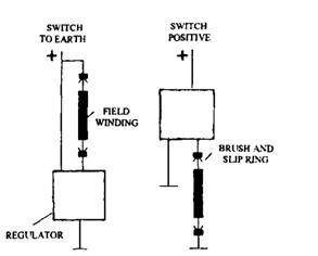
Fig. 14.24. A voltage regulator can switch the field circuit of the supply or earth side.
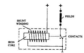
Fig. 14.25. Simplified circuit of a mechanical regulator.
Surge Protection Diode. Failure of the main transistor in a regulator occurs if a poor connection, or similar fault, causes the voltage to suddenly increase when the alternator is charging. A surge protection diode is sometimes installed between the IND lead and earth to prevent this damage to the regulator. The diode conducts when the surge voltage exceeds a set value. Failure of this diode, as it continually conducts, shorts out the field and prevents the alternator from charging.
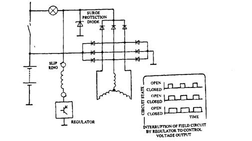
Fig. 14.26. Regulator control of field current and surge protection.
Regulator Construction.
Early alternators incorporated a remotely placed regulator to control the field current by either vibrating contacts or solid state switches. Today most of the vehicles use a micro-electronic regulator housed within the alternator body and is either connected by short leads or push-on terminals to the alternator.
Figure 14.27 illustrates the principle of a regulator in a simplified circuit, built around Zener diode. This type of diode does not conduct any appreciable current until a set voltage is reached, and it conducts freely at this point. Wheh the set voltage is reached, the diode actavties the
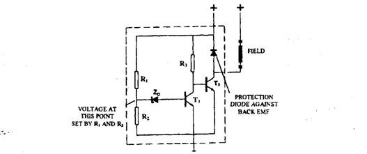
Fig. 14.27. Simplified circuit of a transistorized voltage regulator.
field-switching transistor. Since the Zener diode operates at a voltage less than 14.2 V, resistors Rl and i?2 are installed to reduce the voltage applied to the diode.
More than one transistor is used in this control system, which enables a very small control current provided by the Zener diode to be amplified by the driver transistors to a current sufficient to operate the robust power transistor that switches the full field current. When alternator output voltage is low, current flows from ‘B+’, through resistor R3 to the base circuit of T2 and then to earth. Current flowing through the base circuit of T2 switches-on the transistor and causes the field F to be connected to earth. During this phase, a strong magnetic field is produced. A proportion of the output voltage as it increases, is applied to the Zener diode. At the output voltage of 14.2 V, the diode conducts the current to the base circuit of Ti so that Ti is switched-on. The current now flows freely through Ti from R3 so that the base of T2 is robbed of current. Hence, T2 is switched-off and current through the field winding is interrupted. This sequence is summarized in a tabular form as follows :
| Zener diode | Ti | T2 | Field Circuit |
| No flow | Off | On | Closed |
| Flow | On | Off | Open |
When the output voltage falls below its operating value, the Zener diode switches back to a non-conductive state so that the transistors are switched on to re-establish the field circuit. This process is repeated rapidly to give a constant voltage output from the alternator. The diode Di, fitted across the field winding, prevents T2 from the exposure of a high voltage when the field is suddenly interrupted by the rapid switching of T2.
Voltage-sensingCircuits.
Since the alternator is remotely located in the circuit away from the battery, supply of energy to other equipment alters the p.d. sensed by the regulator installed in the alternator. Therefore, a separate lead is sometimes taken directly from the battery to the regulator to sense the battery p.d. without any alteration in the voltage. This system is called battery sensing.
An alternative system, called machine sensing, has an internally connected lead between the regulator and the IND terminal of the alternator. This system limits alternator output to the regulated voltage irrespective of external loads connected to the battery.
Battery-sensed Regulator.
In the circuit, shown in Fig. 14.28, an alternator is fitted with a Lucas 8TR regulator to sense the battery voltage. This regulator uses three transistors and operates in a way similar to the systems shown in the figure. The cable, connected between the
battery and the regulator terminal B+, acts as the sensing lead. Voltage applied to B+ signals the Zener diode to start conducting.
Machine-sensed Regulator.
When this layout uses a Lucas 8TR unit, the regulator has a circuit similar to Fig. 14.28 except the regulation lead B+ is internally connected to the ‘+’ terminal. This arrangement senses the voltage given at the ‘IND’ end of the field winding. The regulator has three leads ‘+’ (yellow), ‘F’ (green) and’-’ (black). Later versions of the regulator, such as Lucas 14TR, uses a Darlington amplifier to perform the heavy-duty switching of the field winding. A typical machine-sensed circuit is shown in Fig. 14.29.
Two additional resistors R3 and R5 and two capacitors Ci and C2 are used. This sub-circuit permits the regulator to oscillate at a frequency controlled by the internal time-constant

Fig. 14.29. Machine-sensed regulator (Lucas).
provided by the charge-discharge action of the capacitors. This ensures the rapid switching-on and -off of the transistor T”3. The regulator controls the output voltage to modulate the mark-space ratio, i.e. the ratio between the closed and open periods (Fig. 14.29). The spade connectors, used in Lucas type regulators 16TR-21 TR, improve reliability by eliminating interconnecting cables, which forms an integral circuit with stator and field system.
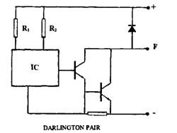
Fig. 14.30. Circuit diagram of the Bosch EL regulator.
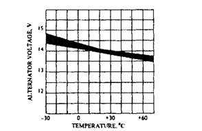
Fig. 14.31. Variation of the regulator response with temperature.
The circuit diagram of a Bosch EL type hybrid regulator is shown in Fig. 14.30. This regulator comes as a complete unit with the carbon brushes and a brush box. The regulator is mounted on the back of an alternator. The hybrid system connects discrete components on a ceramic plate using film techniques. The heart of the regulator is an IC containing the sensing elements and temperature compensation components. The IC controls an output stage such as a Darlington pair. This approach results in a very compact device, which is very reliable due to less number of components and connections. The variation of the regulator response with temperature is presented in Fig. 14.31.
Over-voltage protection is also included in some applications to prevent damage to electronic components. In a vehicle battery system, the alternator voltage does not often exceed above 20 V due to the low resistance and swamping effect of the battery, even in the event of regulator failure. If the alternator is run with the battery disconnected (which is not recommended), a heavy duty Zener diode connected across the output provides some protection. The Zener diode conducts and causes the system voltage to be kept within reasonable limits, when the system voltage exceeds its breakdown figure.
14.8.6.
Alternator-Characteristics
Characteristics curves of the alternator arejjletted as output current (at stabilised voltage) against alternator rpm, and input power against input rpm. Figure 14.32 illustrates typical alternator characteristic curves, which are plotted under specific conditions, such as regulated output veltage, and constant temperature (300 K). The curve shown in Fig. 14.32 corresponds for an~a!ternator suitable for the example application given in section 14.6. To understand the performance characteristics of an alternator, it is common to observe on the curves
(a) cut in speed,
(b) idle speed range,
(c) speed at which two-thirds of rated output is reached,
(d) rated output speed,
(e) maximum speed,
(/) idle current output range,
ig) current at two-thirds of rated output,
(h) rated output, and
(i) maximum output. The graphs are most often referred to determine
the alternator size for a specific application. The power curve helps to decide the type of drive belt needed to transmit the power or torque to the alternator. The power curve and the current curve can be used together to determine the efficiency of the alternator. At any particular speed when producing maximum output for that speed, the efficiency of any machine is calculated from :
Efficiency = (power out/power in) 100%.
In this case at 8000 rpm,
Power out = 14 V x 70 A = 980 W
Power in = 2200 W
Therefore, efficiency = (980/2200) x 100% = 45%.
Efficiency at two-thirds of maximum output:
Power out = 14 V x 45 A = 630 W
Power in = 1000 W
Therefore, efficiency = 63%.
These figures illustrate the power lost in the generation process. Iron losses, copper losses, windage and friction mainly contribute to inefficiency. The energy is lost as heat.
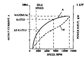
Fig. 14.32. Typical alternator characteristic curve.
