10.5.
Filtration Arrangements
A typical installation of primary (coarse) and secondary (fine) filters comprises a primary filter combined with the sedimentor. The primary filter protects the feed pump against the harmful abrasives. Because it is installed on the suction side of the pump, it must offer a minimum resistance to flow to avoid fuel starvation, and therefore is fairly coarse. The secondary filter removes the very fine particles that have passed through the primary. Its paper element therefore has a very fine and dense structure.
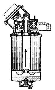
A manual primer pump is often fitted to the filter head (Fig. 10.4). It is normally used after any maintenance operation like change of element due to which air enters into the system. During operation of the engine, the fuel by passes the primer pump, to eliminate any possibility of restriction to flow. Venting procedures for removal of air vary from system to system. Normally a non-return valve is placed in the vent. Electrical heater elements, usually of about 200-
300 W rating are installed in the filter to prevent it from being clogged by wax. Thermostatic control is incorporated to prevent overheating of the fuel. Although the primary filter is the usual location for a heater but in some vehicles, it may be installed further upstream. When a combined filter and water separator is used, the heater coil is either surrounded the inlet or is installed immediately above or beneath the filter element.

Fig. 10.4. Primer pump with the filter.
Fine filters for secondary application generally of simple design, comprising a cast head having the inlet and outlet passages. The filter chamber, mounted beneath the head is usually secured by an axial bolt and nut. This chamber houses a cylindrical filter element, of the pleated or star section, stacked spaced disc, or coiled V-section paper. Normally water is removed completely by the primary filter, however, as a safety many manufacturers incorporate a water trap and drain plug in the base of the secondary filter.
The filter element of an agglomerate type diesel fuel filter unit (Fig. 10.4), produced by Lucas, comprises of two strips of crepe paper wound on to a tubular core, which is contained co-axially within a cartage or metal canister. One of the strips is coated with the bonding agent along one edge of one side and the other edge of the other side. During the winding operation, they bond together to form a multi-V section. Crepe paper is used to provide a flow path between the layers of paper. Techno-car filter (Fig. 10.5) incorporates in its head a manual priming pump and a heater assembly.. The latter comprises five extremely compact ceramic based elements, the electrical resistance of which increases logarithmically with temperature. An electronic control unit switches off the heater when the temperature of the fuel is above 275 K.

Fig. 10.5. Techno-car filter.
