28.5.
Drum Brakes
28.5.1.
Brake Layouts
There are two types of drum brakes, such as externally contracting and internally expanding. External contracting brakes are preferred for automatic gearboxes. The internal expanding type, along with a drum, is commonly used in braking systems of vehicles. The drum brakes, used with light vehicles, are hydraulically operated. These brakes are commonly used for the rear wheels to complement a disc system at the front. This disc/drum layout permits the front wheels to undertake more braking effort. In addition, the compatibility of a mechanical hand-brake with a drum brake makes this type an obvious option for rear brakes.
Various shoe arrangements in use include :
• Leading and trailing shoe (L&T)
• Two leading shoe (2LS)
• Duo-servo.
28.5.2.
Leading and Trailing Shoe (L&T)
The layout of a leading and trailing shoe brake is presented in Fig. 28.14. This arrangement uses a pair of shoes pivoted at a common anchor point. The free ends of both shoes are radially forced against the inside surface of the brake-drum using a double piston/cylinder expander.
When the brake is applied with the vehicle stationary, hydraulic pressure pushes each shoe outwards and an equal force is applied by each shoe to the drum. But this applied force does not remain equal when the vehicle is moving (Fig. 28.14A). The drag of the moving drum on the friction linings causes one shoe to be applied hard and the other to be pushed towards the ‘off position. The shoe that does more work is called the leading shoe, and the other shoe is called the trailing shoe. The rate of lining wear of leading shoe is higher as it does more work than the trailing shoe. Therefore, leading shoe reaches its wear limit well before the trailing shoe, unless a thicker lining is used. If the direction of the drum is reversed, the leading shoe, however, is converted into a trailing shoe.
The unequal wear pattern can be taken up by the floating pistons in the wheel cylinder in some layouts as shown in Fig. 28.14A. Otherwise, some provision is incorporated to adjust the brake shoes so that they are always centralized with respect to the drum (Fig. 28.14B).

Fig. 28.14. Leading- and trailing-shoe drum-brake.
Figure 28.15 illustrates the three factors that vary the amount of self-servo acting on a leading shoe.

Fig. 28.15. Factors affecting self-servo torque.
These include :
(a) Position of shoe tip. The movement of leading edge of the friction lining towards the hydraulic expander increases the self-serve action.
(b) Coefficient of friction (u) of the lining. An increase in the value of u also increases self-servo action.
(c) Position of the shoe anchor. Movement of the anchor towards the centre of the drum increases the self-servo action.
Therefore the L&T shoe brake that has a large self-servo characteristic develops high braking power that means it has a large drum drag for a given application of force. This is made possible due to the use of energy from drum rotation to minimize the effort applied by the shoe expander.
Conversely, the negative servo action on the trailing shoe must be minimized for obtaining powerful braking action. In order to achieve this, the friction lining of the trailing shoe is normally placed nearer to the expander than in the case of the leading shoe. When this feature is incorporated, proper attention must be given during reassembling the brake, otherwise if the shoes are reversed, a fierce braking action with possible grab (lockup) results during application.
Because the self-servo action relies on friction, any fall-off in the friction value seriously affects brake performance. Normally this happens when serious brake fade occurs. Another drawback of using a high self-servo feature is that the changes in braking power occur with the variation of the applied force to the shoe. Ideally the ratio of drum drag to the applied force should be constant as this provides a progressive braking action. When this is not the case, as was with many L&T shoe brakes used in the past, the brake power increases with pedal pressure, often locking the brake without warming.
Figure 28.16 illustrates an L&T shoe brake incorporated with a wedge-type adjuster. In this configuration, the brake shoes butt against the adjuster unit that acts as a fixed anchor for the shoes. This enables both shoes to float up and down freely in the anchor. This arrangement permits shoe centralization and also reduces the tendency of the brake to grab. When a brake in this arrangement is applied, the two shoes are pushed outwards to contact the drum. Rotation of the drum forces the leading shoe directly against the anchor. The reaction of the trailing shoe is transmitted through the expander to the leading shoe. This asymmetrical layout needs attention to ensure that the linings are refitted in their correct positions after an overhaul. Alsor care must be taken not to interchange the back-plates with their shoes from left to right and vice versa during assembly.
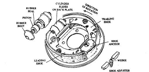
Fig. 28.16. Leading and trailing shoe brake arrangement.
28.5.3:~
Two Leading Shoe Brake (2LS)
The 2LS system was in use for front brakes of vehicles before the adoption of the disc system. Each shoe of the 2LS arrangement uses its own expander; therefore both shoes can have self-servo action (Fig. 28.17). An interlinking pipe fitted behind the back-plate provides an equal hydraulic” pressure to each single-acting cylinder. Since the cylinder housings act as shoe anchors for the floating shoes, the cylinders are rigidly fixed to the back-plate.
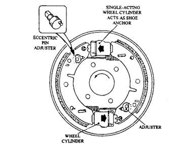
Fig. 28.17. Two leading shoe brake.
L&T shoe brake offers the following advantages over 2LS brakes:
(a) Even lining wear. Because both shoes perform an equal amount of work, the brake runs cooler needing relatively less adjustment and has a long life.
(6) Equal self-servo action. Two effective shoes provide a more powerful and stable brake.
(c) Greater resistance to fade. Since both the shoes share the braking equally, the self-servo action on this shoe can be reduced so that a more progressive braking action, which is less sensitive to heat, is achieved.
One disadvantage of the 2LS type is that unless a special double-acting linkage is incorporated, both shoes change to trailing shoes during backward movement of the car. To compensate for this problem L&T type brakes are used as rear brakes.
28.5.4.
Duo-servo Brake
This brake arrangement is also known as the self-energizing brake. Although this is a very powerful brake, its effectiveness reduces severely with the decrease in the friction value. A hydraulically operated duo-servo brake is shown in Fig. 28.18. The principle of operation is based on the utilization of drum energy to considerably boost the force applied on the brakes by the driver.
When the leading shoe is pushed to contact the forward-moving drum, it rotates partially with the drum due to the frictional force. This shoe movement, produced by this self-wrapping action, is conveyed through a floating adjuster to the trailing shoe so that the shoe is brought into contact with the drum. The force applied by the expander is supplemented by the self-energizing action of both shoes.
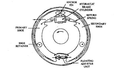
Fig. 28.18. Duo-servo brake.
To minimize the delay in application of the self-energization action, the trailing shoe is held on the anchor pin by a stronger return spring so that the expander only moves the leadingshoe. In this arrangement, the leading shoe is called the primary shoe, because this shoe is made to contact the drum before the secondary shoe.
28.5.5.
Automatic Adjusters
Various types of automatic adjusters are used to position the shoes at the correct distance from the drum. Since the adjustment of front disc brakes is automatic, most modern rear drum brakes are provided with separate automatic adjusters. Of the two main types of adjusters in use, one type takes up the wear during operation of the footbrake and the other is controlled by handbrake operation.
Footbrake-operated.
Figure 28.19 illustrates one of the several arrangements to adjust wear using the footbrake. In this layout, a cross-strut is retained onto one shoe by a spring and
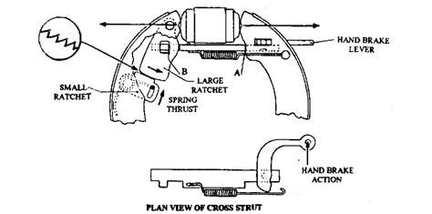
Fig. 28.19. Automatic brake-adjusting mechanism.
two ratchfts are mounted on the other shoe. A spring acting on the small ratchet pushes the fine saw-like teeth towards the large ratchet, which uses a slot to receive the cross-strut. With a correctly adjusted brake, a small clearance exists only at the location B.
In case the shoe-to-drum clearance is small, the ratchets move with the shoe during operation of the brake, but when the outwards movement of the shoes exceeds the clearance at B, the strut holds back the large ratchet so that it jumps a tooth. Consequently, when the brake is released the return movement of the shoe is less then the previous.
The handbrake in the normal operation allows a cranked lever to act directly on one shoe. The reaction on the pivot pushes the strut against the locked ratchets to expand the other shoe.
Handbrake-operated.
In this arrangement, the movement of the handbrake is used to adjust lining wear. In one of the layouts, shown in Fig. 28.20, the shoes are held apart to provide the correct shoe-to-drum clearance by a threaded strut, which is expanded by a ratchet toothed wheel. The wheel is moved by a pawl connected to the handbrake lever.
The movement of the handbrake lever increases with lining wear. When this movement exceeds a set limit, the pawl jumps a tooth on the ratchet. The handbrake action following this relative tooth-to-pawl movement lengthens the threaded strut and sets the shoes closer to the drum.
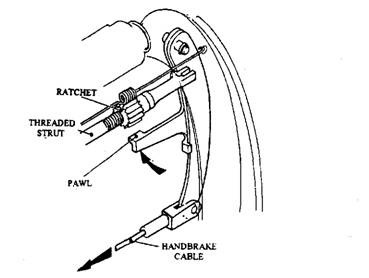
Fig. 28.20. Automatic adjuster-handbrake operated.
Duo-servo type brakes utilize self-wrapping movement to control the length of the floating adjuster. In some pawl and ratchet arrangements, the forward motion of the car carryout the adjustment, whereas others only achieve in reverse. Sometimes drum removal becomes difficult if grooves are formed on the drums. To accommodate this, a hole is often provided in the back-plate near the automatic adjuster.
28.5.6.
Hydraulic-operated Drum-brake System
The drum-brake arrangements are shown in Fig. 28.21. To expand the shoes hydraulically, two separate pistons are fitted in a wheel-cylinder fixed rigidly to the back-plate. An anchor pin, also rigidly mounted on the back-plate, arrests the rotation of the shoe with drum and resists the full braking torque. A strong spring, secured on the back-plate side of the shoe, returns the fluid and shoes when the brake is released. A snail cam or eccentric is positioned behind each shoe for manual adjustment of the shoes. This cam can be partially rotated with the aid of a wrench jx> set each shoe as close to the drum as possible without causing excessive binding (rubbing).
Wheel-cylinder Shoe-expander.
A leading-and-trailing-shoe arrangement (Fig. 28.14) uses a double-piston/cylinder expander in which the trapped fluid pushes simultaneously both pistons outwards so that an equal actuating force is applied on each shoe. A floating expander effect is achieved as the fluid is inactive to the positioning of the pistons and responds only to the reaction of the pistons against the shoes. Consequently, if one shoe lining wears out more than the other both pistons move over to one side and equally share the actuating force. Rubber seals are installed to prevent fluid leakage.
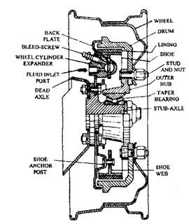
Fig. 28.21. Drum-brake arrangement.
Anchor Abutments.
An anchor abutment is mounted onto the back-plate on the side opposite to the expander unit. The anchor provides a hinge for the shoes. It may be a single post, double-pin post, or a sliding abutment block that prevents the shoes from rotating with the drum when the brakes are applied. The single, type and double type anchors are used for light and heavy-duty vehicles respectively. Occasionally, for light and medium-duty applications, the sliding abutment types is preferred because it is self-centralizing and also to some extent compensates for uneven lining wear.
Retraction Springs.
These coil springs, also known as pull-off springs, are used to pull the shoes away from the drum to prevent any possible shoe drag when the hydraulic pressure is released. Simultaneously, retraction of the shoes pushes the wheel-cylinder expander pistons together and displaces brake fluid back to the master-cylinder.
Back-plate.
The back-plate is also called as the torque-plate as it absorbs the entire braking torque reaction of the shoes. It is usually a pressed-steel, which is ribbed to increase rigidity. The plate is bolted to the angle flange and provides support for the cylinder expander, anchor abutment, and brake-shoes. It also functions as a dust-shield to protect the drum-and-shoe assembly from dirt and mud.
Brake-shoes.
These shoes are rectangular steel strips shaped so as to match the inside curvature of the drum. A steel web is welded behind and in the middle of the shoe sole to form a T’ section for rigidity. The expander end of the shoe is known as the ‘toe’ and the anchor end as the ‘heel’. Both toe and heel may be flat, curved, or may have a semi-circular groove formed to position the expander or anchor abutments.
Brake Linings.
The lining materials are usually either woven or molded asbestos impregnated with natural resins, bitumen, and drying oils, or with synthetic resins. These materials can withstand high operating temperatures while almost maintaining their frictional properties (refer section 28.7). The linings for cars and light-duty applications are bonded to the shoes by adhesives with heat treatment. In commercial vehicles the linings are generally riveted to the shoes.
Brake-drums.
The brake-drum is basically a shallow cylinder with a flange at one end. It is bolted concentrically to the axle-hub. These are generally made of cast or malleable iron. It has one”or two ribs circumferentially on the outside near its mouth to provide rigidity against radial expanding forces and to improve heat dissipation. The circumference of the drum is internally machined to provide a smooth contact with the brake lining.
Steady-post and Rest.
The steady-post keeps the brake-shoe square with the drum. The web of the shoe bears against the steady-post on the back-plate and hence counteracts the offset pull of retraction springs of the shoe.
Another type of steady-rest uses either a coil spring or a leaf spring that presses the shoe onto the pressed-out or riveted-block platform on the back-plate. The coil spring is retained in position on the pin by means of a slotted washer pressed down and turned under the cross-piece on the head of the pin. The leaf spring arrangement incorporates a wavy spring clip that is slotted to snap into position when it is compressed and pushed between the cross-piece of the pin and the shoe web.
28.5.7.
Cam-operated Drum-brakes
Initially almost all the drum-brakes were cam-operated. The cam is used to force the shoes against the drum. Foot-brake shoe-expanders for cars are now mostly hydraulically operated. Today the cam-operated expander is only used in large trucks, and particularly in articulated trailers. However, cams are preferred in parking-brake mechanisms in both drum and disc layauts.
The disc-type cams use a plate in the cam-type brake-shoe expander. The plate rotates about an axis perpendicular to its plane. The profile of the plate provides a reciprocating motion to its follower, the shoe, which bears against the cam edge.
The shoe-expander provides a suitable force ratio between the input effort and the output brake-shoe load. During initial period of braking, only the tension of the pull-off springs and friction in the mechanism are required to be overcome, hence a low force ratio is needed. But when the shoes are actually pressing hard against the drum and further braking is necessary, a progressively increasing force ratio is necessary. These requirements are met through variable-movement ratio cams.
Flat and Oval Cams.
One version of the variable-movement ratio cam (Fig. 28.22) is the flat-faced cam. The force applied by the cam is perpendicular to the shoe at the contact point and the force acts at a maximum distance from the cam’s axis when the cam and shoe flat faces are parallel before braking. As the cam rotates, this distance decreases since the contact point moves towards the centre of the shoe face. Consequently, the force ratio becomes greater. The force ratio can be increased even further for some applications, by using an oval cam profile in contact with the flat shoe faces.
‘S’ Cams.
Oval cam profiles are suitable only when friction linings are of normal thicknesses and the point of contact on the shoe follower face does not alter appreciably with wear. For commercial vehicles heavy-duty thick linings (12 to 20 mm) with constant-movement-ratio cams (Fig. 28.23)
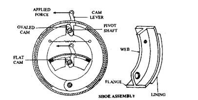
Fig. 28.22. Fixed flat and oval cam.
acting on rollers are used. These two-lobe cams are known as’S’ cams, and have a profile of either an Archimedean spiral or an involute curve. With this shape, the shoes are displaced in direct proportion to the cam lever angular movement from the unworn to the fully worn lining condition that means a constant rate of shoe movement is achieved.
Fixed and Floating Cams.
Since leading shoes work harder than trailing shoes,’the latter wear less. With a correctly adjusted fixed cam, the leading shoe wears more than the trailing shoe, due to which the shoe tip force on the leading
shoe is reduced until the trailing shoe has worn down by the same amount. So braking takes place in phases of leading mode followed by trailing mode thus equalizing the shoe wear. This is known as the equal-work condition.
Equal load on the shoe tips can only be obtained with a different amount of cam lift for each shoe. This is possible by having a floating cam that automatically adjusts its position with the state of lining wear (Fig. 28.24). Usually, braking is more effective with a floating cam, but the total lining wear between the two shoes becomes extremely uneven.
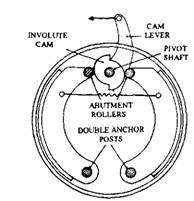
Fig. 28.23. Fixed involute ‘S’ cam.
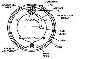
Fig. 28.24. Floating flat cam.
