Binary Offset Carrier Modulation
The Galileo signals and the planned modernized GPS signals inherit improved performance compared to the existing GPS signals. One of the improvements is the introduction of the binary offset carrier (BOC) modulation. BOC modulations offer two independent design parameters
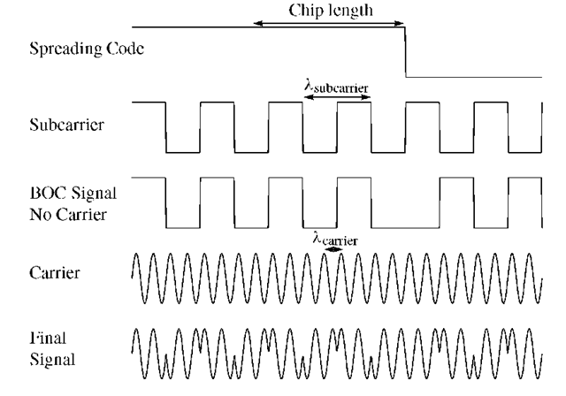
FIGURE 3.3. Spreading code, subcarrier, carrier, and signal as result of the BOC modulation principle. This figure does not show the navigation data.
These two parameters provide freedom to concentrate signal power within specific parts of the allocated band to reduce interference with the reception of other signals. Furthermore, the redundancy in the upper and lower sidebands of BOC modulations offers practical advantages in receiver processing for signal acquisition, code tracking, carrier tracking, and data demodulation; see Betz (2002).
Most Galileo signals come in pairs: a data signal and a data-free signal. They are aligned in phase and consequently have the same Doppler frequency.
A BOC(m, n) signal is created by modulating a sine wave carrier with the product of a PRN spreading code and a square wave subcarrier having each binary ±1 values, see Figure 3.3. The parameter m stands for the ratio between the subcarrier frequency and the reference frequency![]() and n stands for the ratio between the code rate and
and n stands for the ratio between the code rate and![]() Thus, BOC(10, 5) means a 10.23 MHz subcarrier frequency and a 5.115 MHz code rate.
Thus, BOC(10, 5) means a 10.23 MHz subcarrier frequency and a 5.115 MHz code rate.
The result of the subcarrier modulation is to split the classical BPSK spectrum in two symmetrical components with no remaining power on carrier frequency; see Martin et al. (2003).
The product is a symmetric split spectrum with two main lobes shifted from the carrier frequency by the amount equal to the subcarrier frequency; see Figure 3.4. We concentrate on BOC(m, n) = BOC(1, 1) as this is likely to be used by the L1 signal transmitted by Galileo.
The ACF of BOC signals has a profile with more peaks that may be tracked. For BOC signals it is important to make sure the channel is tracking the main peak of the correlation pattern. So additional correlators are needed for measuring the correlation profile at half a subcarrier phase from prompt correlator at either side.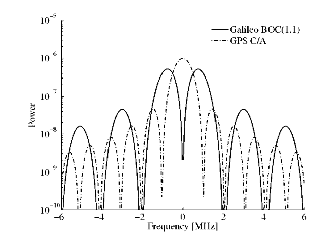
FIGURE 3.4. GPS C/A and Galileo BOC(1,1) sharing L1 spectrum. Center frequency is 1575.42 MHz.
If one of the output values of these so-called very early and very late correlators is higher than the punctual correlation, the channel is tracking a side peak and corrective action is taken. According to Nunes & Sousa & Leitao (2004), the ACF for BOC(pn, n) with
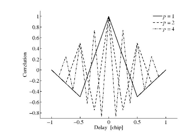
This ACF is plotted in Figure 3.5. For p = 1 this is
The ACF for the BOC(n, n) signal with bandwidth b is given as [see Winkel (2000), Equation (2.68)]
and the sine integral is defined as
FIGURE 3.5. ACF for the BOC(pn, n) signal as function of delay![]() and p.
and p.
If we plot the function![]() we get a result similar to the one in Figure 3.5 for n = 1, 2, 4.
we get a result similar to the one in Figure 3.5 for n = 1, 2, 4.
The BOC ACF profile results in a DLL discriminator curve that is a bit more complicated than that of GPS. Figure 3.6 shows the ideal band-unlimited correlation function for both a C/A code signal and a BOC(1,1) signal. Shown as well are early minus late discriminator curves for a chip spacing of 0.5 chip.
We observe various facts. Both discriminator curves are linear around the center of the ACF. In both cases the linear region extends from -0.25 to 0.25 chip code offset. The slope of the BOC discriminator in the linear region is three times the slope of the C/A discriminator. The C/A code discriminator output is used to adjust the code NCO to align the code phase better with the incoming signal; this adjustment will succeed for tracking errors less than 1.25 chips. The C/A dis-criminator is stable in the entire region where the discriminator curve is non-zero and the DLL will converge.
FIGURE 3.6. C/A code and BOC(1,1) ACF and early minus late discriminator curves.
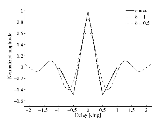
FIGURE 3.7. ACF for bandlimited BOC(1,1) signal. The normalized bandlimit is b = 0.5, 1, and![]() The function for
The function for![]() is identical to BOC(1,1) in Figure 3.5.
is identical to BOC(1,1) in Figure 3.5.
The BOC discriminator has stable regions next to the linear region as well, but tracking errors in the outer regions (absolute errors less than 1.25 and greater than 0.625 chip) will cause the DLL to diverge and lose lock.
Figure 3.4 is a nice illustration of the fact that the GPS C/A code and the Galileo BOC( 1,1) modulation share the L1 spectrum. Still it is possible to separate the two signals.
According to Betz (2002), the power spectral density of the![]() centered at the origin is
centered at the origin is
The number of negative and positive peaks is![]() in the ACF separated in delay by
in the ACF separated in delay by![]()
For the Galileo BOC(1,1) data-carrying signal, the code length is 4092 chips, 1.023 MHz band frequency (4 ms period time), 250 Hz symbol rate (1 code period per symbol), ~ 85% of signal power within ~ 4 MHz bandwidth.
Figure 3.7 shows the ACF for bandlimited BOC(1,1) signals. For limited bandwidth the peak value is less than one; this reflects the fact that not all power is available in the signal. Part of the power is blocked by the bandlimiting. For b = 1 the bandlimiting results in a slight rounding off at the edges of the ACF. For b = 0.5 the frequencies lower than twice the square wave frequency are stopped by the filter. This results in oscillations outside the chip length region. This could lead to undesirable side-lobe effects in case of multipath.
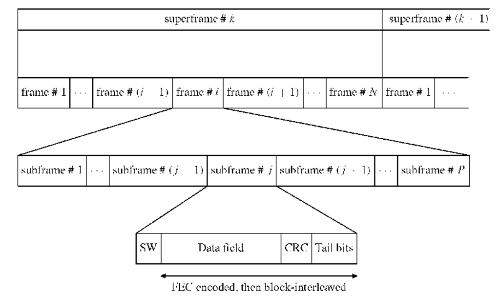
FIGURE 3.8. Navigation message structure. CRC is computed over the data field.

![tmp2D493_thumb[2] tmp2D493_thumb[2]](http://what-when-how.com/wp-content/uploads/2012/02/tmp2D493_thumb2_thumb.png)
![tmp2D494_thumb[2] tmp2D494_thumb[2]](http://what-when-how.com/wp-content/uploads/2012/02/tmp2D494_thumb2_thumb.png)
![tmp2D495_thumb[2] tmp2D495_thumb[2]](http://what-when-how.com/wp-content/uploads/2012/02/tmp2D495_thumb2_thumb.png)
![tmp2D500_thumb[2] tmp2D500_thumb[2]](http://what-when-how.com/wp-content/uploads/2012/02/tmp2D500_thumb2_thumb.png)

![tmp2D513_thumb[2] tmp2D513_thumb[2]](http://what-when-how.com/wp-content/uploads/2012/02/tmp2D513_thumb2_thumb.png)
