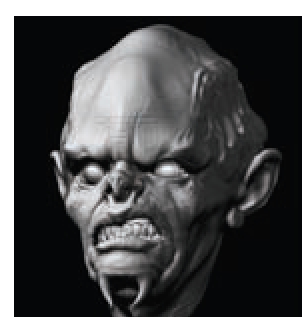
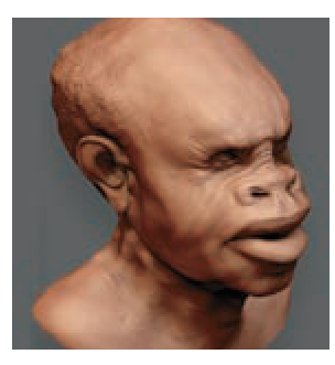
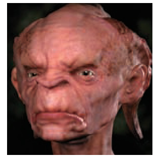
After sculpting and painting your character in ZBrush, you may want to transfer your work into another application such as Maya or 3ds Max for animation and rendering. Your final product may be for film, video games, print, or even a 3D rapid prototype model created on a 3D printer. By giving you a method for rendering your ZBrush work in other applications, Pixologic has opened the door for ZBrush to become a staple in professional entertainment industry pipelines.
Although most applications cannot render millions of polygons—and at this time no application can animate a mesh with such a high polygon count—you can still use your ZBrush asset in a visual effects or game pipeline. By using difference mapping, you can re-create your high-polygon digital sculpture in a suitable renderer. Decimation, on the other hand, offers the ability to export your actual 3D model with all the high-frequency detail while maintaining a workable file size. This ability to maintain detail within a workable file size is very important when the final product is to be 3D printed to create a physical model from 3D data.
Before we proceed, it is important to understand the concept of difference maps and how they function. In this context, the term difference mapping refers to texture maps generated by calculating the difference between two surfaces, usually a high-resolution polygon mesh and a low-polygon counterpart placed together in world space so the program can find the corresponding point on the high-res mesh that matches the same point on the low-res mesh.
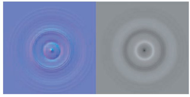
ZBrush will calculate the differences between a high-res mesh and a low-res surface and produce a value appropriate for the kind of map being generated. The resulting map can be used in a third-party renderer to re-create the look of the highly detailed ZBrush model. ZBrush can create two kinds of difference maps: displacement maps and normal maps (Figure 9.1). In this topic, we’ll focus on displacement mapping.
Displacement Maps
Displacement maps create high-resolution details by physically displacing the geometry at render time. The model is sliced into millions of triangles by the renderer in a process called tessellation. The surface is then pushed in or out based on a grayscale value in the displacement map. Some renderers perform subpixel displacement, which is a re-tessellation of the surface into micropolygons or microtriangles to support even finer details. The important thing to understand is that displacement mapping requires that the geometry be heavily tessellated at render time.
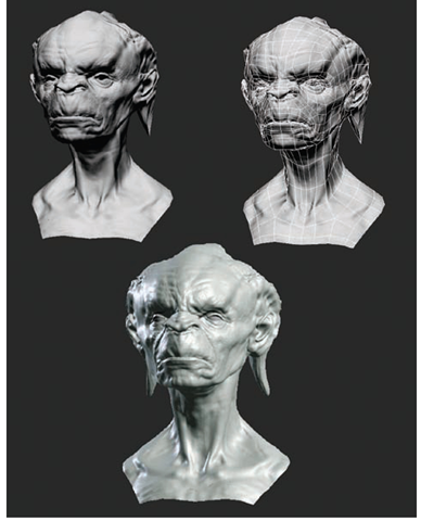
Because these maps create actual geometry, they are heavy on processing power and can involve long render times. They also offer superior results compared with any of the other mapping types since the rendered mesh is extremely dense and carries all the details of the surface and silhouette. This is in contrast to normal mapping, which only creates the look of a highly detailed surface without changing the underlying geometry or polygon count. See Figure 9.2 for an example of normal mapping versus displacement.
ZBrush also enables you to create bump maps by using the Bump Viewer material or by generating a displacement map for use as a bump map. In technical terms, bump maps and displacement maps are iden-tical—it is the renderer that reads and displays them differently. Both are grayscale maps with white values representing height and dark areas representing depth. In application, however, bump maps differ from displacement maps in that they do not change the overall silhouette of the surface. Bump maps give the impression of surface detail where there is none by perturbing the surface normal of the mapped faces. Because bump maps don’t require heavy subdivision at render time, they render much faster than displacement maps but do not provide high-quality results since the profiles are not altered. Bump maps can be extremely successful when combined with displacement maps. See the section “Applying Bump Maps in Maya” later in this topic for more information.
Figure 9.1 A normal map (right) and a displacement map (left)
Figure 9.2 Two renders of the same character. On the normal mapping example at the top, notice how the internal forms appear highly detailed while the silhouettes still display polygon faceting. The image in the upper right shows the polygon mesh itself. The displaced render at the bottom contains all the fine details on the surface as well as a displaced profile with no faceting.
Normal Maps
Normal maps are similar to bump maps in that they do not alter the profiles but they offer more realistic shading on the surface details. While bump maps perturb the surface normal, a normal map replaces it entirely with an RGB value. This vector value can represent the X, Y, and Z coordinates of the surface normal of the high-res mesh and allows for highly realistic detailed surfaces but won’t affect the low-poly faceting of the shape’s edges. Normal maps are used heavily in video game applications.
