When you’re preparing a model for sculpting and displacement extraction in ZBrush, the mesh needs to be clean. By clean, I mean it should consist of all quads (or at least nearly all quads). Avoid triangles, poles (points where five edges or more meet), and n-gons (faces with more than four vertices). If you find you must have a triangle, hide it in an inconspicuous area. Triangles and n-gons may cause artifacts at render time. You also want to ensure your vertices are all welded and that there are no nonmanifold or lamina faces. You can resolve all of these mesh issues by using the cleanup tool. Follow these steps before you start sculpting on the model as they will potentially alter the vertex order of the mesh.
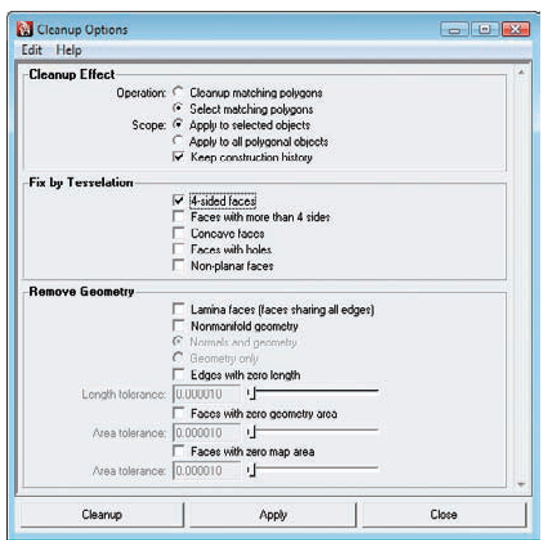
1. Select Polygons + Cleanup + OP to open the Cleanup Options dialog box (Figure 9.47).
2. If you choose Select Matching Polygons in the Cleanup Effect section and check only the 4-Sided Faces option, click the Cleanup button and Maya will select all the quads in your mesh. You can then use Edit + Invert Selection to select the nonquad faces. Often, I will assign another color to these faces to keep them visible and continue working the topology until I have an all-quad mesh.
3. Still in the Cleanup Options dialog box, choose the Cleanup Matching Polygons and select Lamina Faces and Nonmanifold Geometry in the Remove Geometry section.
Click the Cleanup button, and this will resolve any of the issues that often arise when modeling with the Extrude tool. Cleaning up your mesh now can save a lot of headaches later on.
Troubleshooting Renders and Artifacts
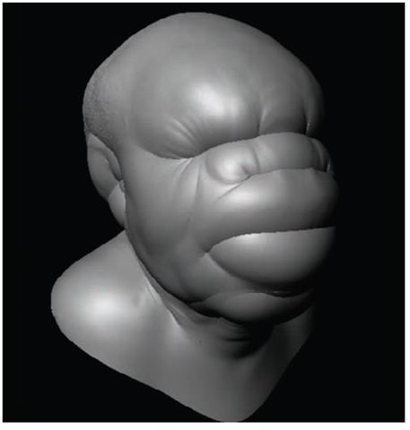
In some cases you may see artifacts in your renders. If you see bloating in your render, that means there is a mistake with the Alpha Gain and Alpha Offset values or the Alpha Detection setting is wrong (Figure 9.48). Usually you have forgotten to set one or both, or the Alpha Offset is not set to -½ Alpha Gain.
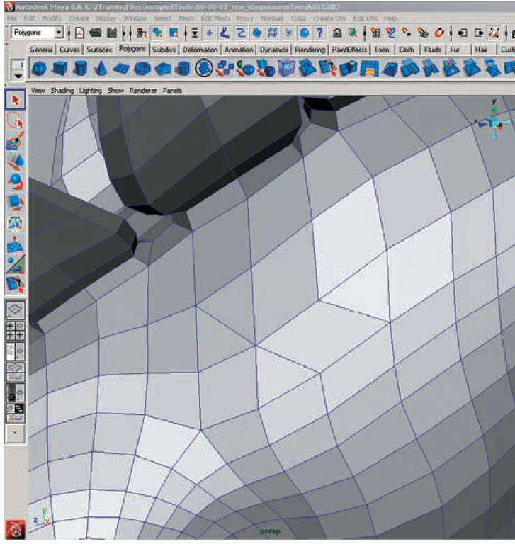
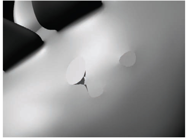
Small spikes on UV seams can be remedied by using the Smooth UV option under Tools + Displacement. Use this only when creating an adaptive map. It has no effect in DPSubPix mode. Many artifacts are caused by bad topology in the underlying mesh. Triangles, poles, or faces with more than four sides can result in surface errors (Figure 9.49). These artifacts should be hidden in inconspicuous places during the modeling process or removed completely. If you find such an artifact on your render, applying a smooth to the mesh before rendering can help (Figure 9.50). Doing so will increase render time, and you may want to lower your Approximation settings as a result.
Figure 9.47 Cleanup Options dialog box
Figure 9.48 The bloating in this render is due to incorrectly set Alpha Gain and Alpha Offset settings.
Figure 9.49 An example of problematic topology
Figure 9.50 Mesh artifacts in render
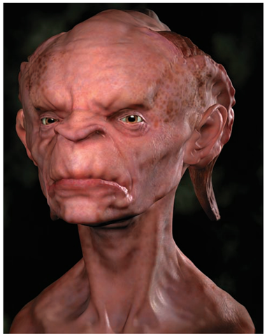
Figure 9.51 The Stingerhead character rendered with displacement and subsurface scattering
In this section, we explored the two major displacement map types that can be exported from ZBrush, and you learned how to set up models and shaders for displacement in Maya. By combining your texture map, displacement, diffuse, and bump maps with a subsurface scattering shader, you can achieve renders like the one shown in Figure 9.51. The ability to capture the high detail of your characters in other renderers allows you to take your work to the next level, breathing life and animation into your work. In the next section, we’ll continue looking at difference maps in ZBrush by discussing normal maps.
Normal Maps
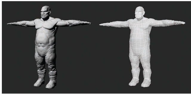
Normal maps are color maps that represent the surface normal direction of any given point on the model. They allow a renderer to create the impression of a highly detailed surface on a low-polygon base. Figure 9.52 shows an example of a normal map and the rendered result on a model.
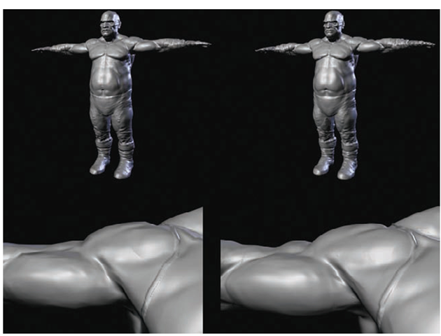
Normal mapping differs from displacement in one major way. While displacement mapping makes actual geometry at render time by subdividing the mesh, normal mapping creates the illusion of a highly detailed surface without changing the geometry. The benefit of this is speed, but the drawback is that the silhouette of the model will not change. In Figure 9.53, the character on the right is displaced while the character on the left is normal mapped. Note how the profiles are still angular on the normal mapped figure.
For this reason it is imperative that the base model be optimized to best represent the overall profiles of the model when you will be normal mapping. If your low-polygon mesh is too low and does not represent the form of the high-res, you will end up with errors in your normal map at worst—or at least a normal map that is unconvincing when displayed on a faceted model.
Normal maps offer a superb way to create the illusion of a highly detailed surface on a low-polygon base. Normal maps are actually generated from bump maps when processing; this process is invisible to the user but understanding it will help you understand the inner workings of the normal map.
Figure 9.52 This character is rendered with a normal map. This mapping method gives the low-polygon mesh seen on the left the appearance of high-frequency details, as shown on the right.
Figure 9.53 The model on the left is normal mapped whereas the right is displaced. Note the visible polygon facets on the silhouette of the normal mapped model (especially in the shoulder) and how the details do not translate into the silhouette.
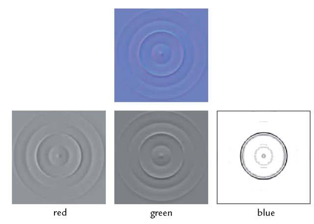
Figure 9.54 The individual channels of a normal map
A normal map is an RGB image file. Each channel of the map (R, G, and B) represents one of the three axes (x, y, and z). In Figure 9.54 the individual channels of a normal map have been isolated to help illustrate this. The Red, or R, channel represents the surface lit from the right; the G channel represents light from above, or the Y direction; and B is light shining down the z-axis.
