14.10
The V.29 modem operates in duplex and half-duplex mode. It can operate at data rates of 9600, 7200, and 4800 bits per second (bps). It uses 16-QAM for
data rates of 9600bps, 8-QAM for 7200bps, and 4-PSK for 4800bps. V.27ter
has 4800-bps PSK support. To avoid duplicity, the 4800-bps mode of V.29 is supported from V.27ter. Data transmissions with V.29 and signal details are listed below [ITU-T-V.29 (1988), URL (SPRA073)]:
Baud rate and modulation: 2400 symbols, 16 – QAM for 9600 bps, 8 – QAM
for 7200 bps, and 4-PSK for 4800 bps Center frequency: 1700 ± 1 Hz, and no separate pilot tones are used Power levels: Power output should not exceed 1 mW, and nominal level
-13dBm as per V.2 Signal detection: Signal is detected if signal level is greater than -26dBm
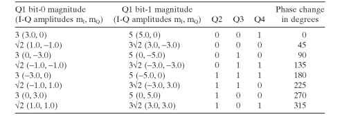
QAM at 9600 bps. To get a 9600 fax rate with 2400 symbols per second, it is required to send 4 bits on each symbol as one group. A group of four consecutive data bits is called quadbits. The first bit (Q1) in time of each quadbit is used to determine the amplitude of the carrier to be transmitted. The second (Q2), third (Q3), and fourth (Q4) bits are used to encode the phase shift. The
Table 14.4. Phase and Relative Amplitude at 9600 bps
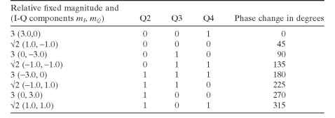
Table 14.5. Phase and Relative Amplitude at 7200 bps

relative amplitude of the transmitted signal element is determined by the first bit (Q1) of the quadbit and the absolute phase of the signal element as shown in Table 14.4.
QAM at 7200 bps. At the fallback rate of 7200 bits per second, the scrambled data stream to be transmitted is divided into consecutive three bits called tribit groups, which works similar to a 9600 fax rate except for amplitude. The relative amplitude is fixed at different phase shifts and takes only 3 and V2 for the phase combinations shown in Table 14.5.
QAM at 4800 bps. At the fallback rate of 4800 bits per second, the scrambled data stream to be transmitted is divided into groups of two consecutive data bits called dibits. The first data bit in time determines the Q2 of the modulator quadbit, and the second data bit determines the Q3 of the modulator quadbit. The Q1 of the modulator quadbit is a data ZERO for each signal element, meaning fixed amplitude. The Q4 is determined by inverting the modulo-2 of
Q2 + Q3 using an Exclusive NOR (XNOR) operation. A QAM at 4800 is not
used.

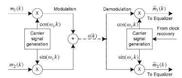
Figure 14.11. QAM modulator and demodulator.
QAM Formulation. The QAM is a very efficient modulation technique in terms of bandwidth usage. In QAM, two quadrature (90 ° phase-shifted) carriers, cos(coc&) and sin(coc&) are amplitude-modulated by two separate information-bearing signals as shown in Fig. 14.11. For input information-bearing sequences m^k) and m2(k), the synthesized digital sequence can be expressed as
![]()
In the above equation, m1 is used here in place of /-component m7; m2 is used in place of Q-component mQ. The spectrum components of the information-bearing signals overlap here. However, the quadrature phase relationship in the carrier components cos(coc&) and sin(coc&) allows the receiving end of the V.29 system to separate the two signals. The demodulation is performed as shown in Fig. 14.11. A digital phase locked loop is used to obtain the carrier component cos(coc&) and to generate sin(coc&). At the receiver, the received sequence is multiplied by the two quadrature carriers. This multiplication results in two signal sequences:

The information-bearing signal components rh1(k) and rh2(k) can be recovered by passing each sequence through a filter that rejects the double-frequency terms centered at 2coc. In the particular V.29 implementation, the carrier frequency (fc) is 1700 Hz and the symbol rate is 2400 Hz.
V.29 Modulation and Demodulation. The block diagram of the V.29 transmitter and receiver will be similar to the V.27 presented in the previous section.
There will be some deviations in the blocks and their functions. Some main deviations are that the scrambler polynomial that operates on the data is different and the QAM mapping for different rates is similar to PSK mapping with different amplitudes. Filter characteristics, bandwidth, and training patterns are also different in V.29.

