14.13
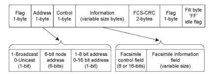
The main purpose of the V.21 FSK modem is to exchange control information between fax modems. This exchange of control information between two fax modems is established using the HDLC protocol. The HDLC protocol specifies a packetization standard for serial links. The basic HDLC structure consists of several frames, each of which is subdivided into many fields. It provides frame labeling, error checking, and confirmation of correctly received information. A basic HDLC frame structure is given below [ITU-T-T.30 (2005), URL
(HDLC) ].
Flag field: The 8-bit HDLC flag sequence is used to denote the beginning and end of the frame. For the facsimile procedure, the flag sequence is

Figure 14.13. HDLC packet format.
used to establish bit and frame synchronization. The trailing flag of one frame may be the leading flag of the next frame. Continued transmission of the flag sequence may be used to signal to the distant terminal that the terminal remains on line but is not currently prepared to proceed with the facsimile procedure. The 8-bit flag sequence is represented in the format “0111 1110″ in binary or “0x7E” in hexadecimal format. In the idle state or in between HDLC frames, fill flags may be transmitted with the flag identifier as “11111111 – byte value 0xFF” or 0x7E. The fill bytes are optional and vary with the implementation. Address field: The length of the address field is of 0, 8, or 16 bits depending on the data link layer protocol. The 8-bit HDLC address field is intended to provide identification of specific terminals in a multipoint arrangement. In the case of transmission on the general switched telephone network, this field is of one byte. Most of the fax implementations use format “11111111″ in binary or “0xFF” in hexadecimal format.
Control field: The 8-bit HDLC control field provides the capability of encoding the commands and responses unique to the facsimile control procedures. The control field byte is in format “1100 X000″ in binary. Where a bit designed as “X” selects two options. X = 0 for nonfinal frames within the procedure and X = 1 for final frames within the procedure. A final frame is defined as the last frame transmitted prior to an expected response from the distant terminal.
Information field: The HDLC information field is of variable length and contains specific information for the control and message interchange between two facsimile terminals. In this recommendation, it is divided into two parts, the facsimile control field (FCF) and the FIF.
Facsimile control field (FCF): The facsimile control field is defined as the first 8 or 16 bits of the HDLC information field. This field contains complete information regarding the type of information being exchanged and the position in the overall sequence. Most fax messages use 8 bits as FCF. The commands that come under the FCF category are DIS, NSF, CSI, TSI, DCS, CFR, TCF, MPS, MCF, EOP, and DCN. An FCF of 16 bits
is used for the optional T.4 error correction mode. The commands that come under the 16-bit FCF category are PPS-NULL, PPS-EOP, PPS-MPS, and PPS-EOM. The 16-bit FCF is represented as FCF- 1 (first 8 bits) and FCF-2 (upper byte). FCF-1 indicates the signal for error correction such as PPS and EOR. FCF-2 indicates postmessage commands in the case of ECM mode. The commands that come under FCF-2 in are NULL, EOP, MPS, and EOM. The FCF-2 field is represented as part of the FIF field in some standards. The bit assignments within the FCF are given in Table 14.8 for some FCF categories as an example. The first bit of FCF is set to “1″ by the originating terminal when it receives a valid DIS signal and is set to “0″ by the called terminal when it receives a valid response to the DIS signal. Facsimile information field (FIF): The facsimile information field is of variable length containing specific information related to facsimile control messages. In many cases, the FIF is followed by the transmission of additional 8-bit octets to clarify on the facsimile procedure. This information for the basic binary-coded system would consist of the definition of the information in the DIS, DCS, digital transmit command (DTC), calling subscriber identification (CSI), TSI, nonstandard facilities command (NSC), nonstandard facilities (NSF), nonstandard setup (NSS), password (PWD) for polling, selective polling (SEP), Subaddress (SUB), file diagnostic message (FDM), CTC, PPS, and PPR signals. Each of these messages will consider several options accommodated in 8-bit combinations. These messages and the details of the FCF and FIF fields are given in the T.30 recommendations [ITU-T-T.30 (2005)]. As shown in Table 14.8, the FIF of different classes/types of data is present. Some possible combinations of the information field are listed below:
• Only the FCF value, no FIF, and the commands/messages that come under
this category are CFR, FTT, MCF, and DCN.
• 16-bit FCF (FCF-1 and FCF-2) and 3 bytes of FIF information, example:
PPS – EOP, PPS – MPS, EOR – MPS, and EOR – EOP.
• FCF and several bytes of FIF to help FCF and data, example: DIS, DCS,
and DIS.
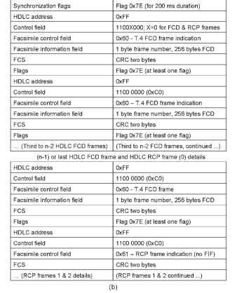
• FCF and FIF as only data, example: optional T.4 error correction mode indicated in Fig. 14.14 (b).
FCS field: Frame check sequence, 16-bit cyclic redundant check-committee consultative international telegraph and telephone (CRC-CCITT) polynomial is used to calculate the CRC. By checking the FCS, the receiver can discover bad data. If the data are correct, it sends an “acknowledge” packet back to the sender. The sender can then send the next frame. If the receiver sends a “negative acknowledge” or simply drops the bad frame, the sender either receives the negative acknowledge or runs into
Table 14.8. FCF and FIF Values for Some Example Messages
| Message | FCF value | FIF field details |
| Facsimile message from the called to the calling terminal | ||
| NSF | 0×04 | 1 – byte country code, and several bytes of |
| nonstandard capabilities of receiving fax | ||
| CSI | 0×02 | phone number of the receiving fax |
| DIS | 0×01 | Several bytes indicating capabilities of |
| called fax | ||
| Facsimile messages from the calling to the called terminal | ||
| NSS | 0xC4/0×44 | country code (1 byte) and several bytes of |
| nonstandard capabilities of calling fax | ||
| device | ||
| TSI | 0xC2/0×42 | phone number of the calling fax |
| DCS | 0xC1/0×41 | capabilities of originating fax terminal |
| Pre – message responses | ||
| CFR | 0×21 | no FIF |
| FTT | 0×22 | no FIF |
| Post – message | commands | |
| MPS | 0xF2/0×72 | no FIF |
| EOP | 0xF4/0×74 | no FIF |
| EOM | 0xF1/0×71 | no FIF |
| Post – message | command responses | |
| MCF | 0×31 | no FIF |
| RTP | 0×32 | no FIF |
| RTN | 0×33 | no FIF |
| DCN | 0x5F/0xDF | no FIF |
| Post – message | commands in ECM | |
| PPS-NULL | FCF-1: 0xFD/0x7D (PPS) | 3 bytes of facsimile information fields |
| FCF – 2: 0×00 (NULL) | FIF field 1 for page count | |
| FIF field 2 indicates partial page block | ||
| count | ||
| FIF filed 3 indicates the number of frames | ||
| transmitted inpartial page or block (up | ||
| to 255 frames) | ||
| PPS – EOP | FCF – 1: 0xFD/0x7D (PPS) | FIF bytes same as in PPS- NULL |
| FCF – 2: 0xF4/74 (EOP) | ||
| PPS – MPS | FCF – 1: 0xFD/0x7D (PPS) | FIF bytes same as in PPS- NULL |
| FCF – 2: 0xF2/72 (MPS) | ||
| PPS – EOM | FCF – 1: 0xFD/0x7D (PPS) | FIF bytes same as in PPS- NULL |
| FCF – 2: 0xF1/71 (EOM) | ||
| RR | 0xF6/0×76 | no FIF |
| CTC | 0xC8/0×48 | two bytes of FIF, same as 1 to 16 bits of |
| DCS | ||
| Post – message | command responses in ECM | |
| PPR | 0x3D/0xBD | FIF of 0 to 255 bits (32 bytes) with each |
| bit indicating the HDLC FCD frame | ||
| delivery status. Bit set as 0 for correct, | ||
| and bit as 1 for wrong delivery | ||
| RNR | 0×37/0xB7 | no FIF, With errors same as PPR |
| CTR | 0×23/0xA3 | no FIF |

First two HDLC FCD frame details for ECM data

Figure 14.14. HDLC format for ECM frames. (a) Representation for FCD and RCP frames. (b) Details on FCD and RCP.

Bit stuffing: Actual binary data may have a sequence of bits that is the same as the flag sequence. Therefore, the data bits sequence must be
transmitted in such a manner that it does not appear to be a frame delimiter/flag sequence. It is achieved using bit stuffing. The bit stuffing is done as follows:
• Transmitter inserts extra “0″ after each consecutive five “1″s inside the frame
• Receiver checks for five consecutive “1″, i.e., “11111″ as a bit pattern
• If the next bit = 0, it is removed.
• If the next two bits are 10, then the flag is detected.
• If the next two bits are11, then the frame is identified as an error.
