8.2
The basic data transport protocol for caller ID is divided into four layers, namely,
1. Physical layer
2. Data link layer
3. Presentation layer
4. Application layer
The first three layers provide the actual data transport, and the application layer is used for caller ID-specific data and signaling for alerting the TE.
8.2.1
Physical Layer
The physical layer provides the interface between the caller ID service and the analog line. The physical layer provides two main functions of data transmission of service-specific information and signaling mainly for alerting the TE.
The data transmission is performed using continuous-phase FSK modulation. Data is always sent as serial binary bits in simplex mode. Data transmission is continuous, and no carrier dropouts are allowed. The start of data transmission must not corrupt the first data bit. The data transmission is
Table 8.1. Data Transmission Characteristics
| Parameter | ETSI-Based Modulations | Telcordia – Based Modulations |
| FSK major distinction Mark (bit-1) Space (bit-0) Data rate Message format Signal generation levels Receiver operating |
FSK as per ITU-T-V.23 1300Hz ± 1.5% 2100Hz ± 1.5% 1200bps ±1% Type – 1: MDMF Type – 2: MDMF -13.5 dBm± 1.5 dB, signal purity 30 dB -8 to -36 dBV (0dBV = 2.2dBm) |
FSK as per Bell 202 1200 ± 12 Hz 2200 ± 22 Hz 1200 ± 12 bps Type-1: SDMF, MDMF, GDMF Type – 2: MDMF, GDMF -13.5 dBm± 1.5 dB, signal purity 30 dB -12 dBm to -36 dBm (space) -12 dBm to -32 dBm (mark) |
stopped immediately after the last bit of the data-link message. The FSK data is sent asynchronously at a signal level of -13.5 dBm in both ETSI and Telcordia recommendations as listed in Table 8.1. This power level is applicable at the central office. The FSK signal level may differ for each country, because of country-specific deviations of overall loudness rating (OLR) as well as because of send and receive gain/loss planning. To get a first-level understanding on ETSI and Telcordia basic specifications, a summary is given in Table 8.1. It is suggested to refer to the ETSI [ETSI ETS 300 659-1 (2001), ETSI ETS 300 778-1 (1997)] and Telcordia [GR-30-CORE (1998)] recommendations for more details on these specifications.
8.2.2
Data Link Layer
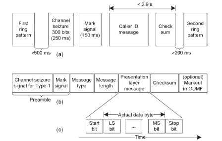
The data link layer is responsible for providing data byte framing (start/stop asynchronous, 8-bit data) and checksum. The data link layer is also responsible for the addition of the preamble, which comprises the channel seizure signal and the mark signal as well as padding of mark bits between bytes for data flow variation.
Note that the definition of the “data link layer” varies slightly between
Telcordia [GR-30-CORE (1998)] and ETSI [ETSI ETS 300 778-1 (1997)-
Annex E]. The ETSI treats the message type byte and message length byte as part of the data link layer, whereas Telcordia treats the message body as a presentation layer message. Telcordia incorporates the message header (type and length bytes) as part of the presentation layer. The Telcordia recommendation refers to the presentation layer as the message assembly layer. Review the complete specifications regarding these differences.
The format of the data sequence at the data link layer is shown in Fig. 8.3(b). The data transmission between rings is presented in Fig 8.1(a) with timing
information for the ETSI recommendation [ETSI ETS 300 659-1 (2001)]. The

Figure 8.3. Data link layer format. (a) Details on data between two rings. (b) Message. (c) Actual data byte format.
data consist of four functional blocks—channel seizure signal, mark signal, caller ID information, and the checksum. For both ETSI [ETSI ETS 300 659-1 (2001)] and Telcordia [GR-30-CORE (1998)], every byte in the sequence (excluding the contents of the preamble, but including the checksum) is framed in an asynchronous manner with each 8-bit word preceded by a start bit (space) and followed by a stop bit (mark). The seizure signal is sent first, followed by the mark signal, and then each byte is sent in sequential order, finally followed by the checksum. No parity is used in the data framing. In the bit transmission, start bit, LS bit . . . , MS bit, and stop bit are sent as illustrated in Fig. 8.3(c). Note that actual byte is represented as stop bit, MS bit . . . LS bit and as start bits.
Channel Seizure Signal. The channel seizure signal is used to signal the start of the data transmission to the CPE or TE to alert for an incoming message, and it conditions the receiver ready for the data. This signal is used to ensure that noise is not falsely identified as a carrier. If the seizure signal is not received, the TE must cease reception, and the next messages are ignored. The seizure signal consists of 300 continuous bits (duration of 250 ms at 1200 bps) of alternating “1″ and “0.” The first bit must be a “0,” and the last must be a “1.” The seizure signal is used only in Type-1 FSK-based on-hook caller ID and is not used in Type-2 call wait ID. The channel seizure bit size is different
in ETSI and Telcordia. In some networks, the ETSI allows for a channel seizure length of 96 to 300 bits [ETSI ETS 300 778-1 (1997)].
Mark Signal. The second signal in the preamble is the mark signal. This signal consists of continuous mark bits. It is used to provide an idle period before the start of the message type byte to allow the receiver to identify the byte. For both ETSI and Telcordia, the same quantity of bits is sent as part of the mark signal. Type-1 is of 180 mark bits (duration of 150 ms at 1200 bps), and Type-2 is of 80 mark bits. Note that the ETSI allows the option of 80 mark bits for Type- 1. The tolerances on the mark signal differ between the two standards. The ETSI allows ±25 bits, and Telcordia allows ±10 bits.
Checksum. The CID information is followed by a checksum for error detection. The checksum is a single byte value, which contains a two’s complement of the modulo-256 sum of all bytes in the message starting from the message type byte up to the end of the message. The channel seizure and mark signals are not included in this checksum. When the TE receives the message, it checks for errors by taking the received checksum byte and adding the modulo-256 sum of all other bytes received in the message. The checksum is verified by summing (modulo-256) all bytes in the message between the message type byte and the checksum. If the contents are correct, the checksum is zero. If the checksum fails, the entire message is discarded without any error correction or message retransmission. The TE must not send any acknowledgment or response back to the stored program control signal (SPCS). The SPCS is part of the central office.
Additional Marks (Padding). To allow for some variations in the arrival of the data to be transmitted, and to ensure that the output sequence remains continuous, a small quantity of additional marks may be added between bytes. This quantity is treated differently between the ETSI and Telcordia. The ETSI allows for additional marks between any bytes within the message [ETSI ETS 300 778-1 (1997)-Annex E], whereas Telcordia allows for insertion of additional marks between selected bytes only [GR-30-CORE (1998)]. It is an objective of the Telcordia specification that no additional marks be inserted between bytes in a parameter message. For example, mark bits (0-10) can be transmitted between message type byte and message length byte, or between parameter type and parameter length. Inserting the additional marks between parameter messages bytes is not allowed.
The number of extra mark bits (not including the stop bit) should be between 0 and 10 bits. These bits are added after the stop bit and before the start bit of the next byte. Additional marks are not permitted in the generic data message format (GDMF) payload used by Telcordia. In GDMF, to prevent corruption of the final stop bit after the checksum or last byte of GDMF, and hence destruction of the checksum, additional marks (markout) may also be used following the checksum.
8.2.3
Presentation Layer
The presentation layer is responsible for the framing of the application-specific data for provision to the data link layer. Data can be organized according to three possible formats: single data message format (SDMF), multiple data message format (MDMF), and GDMF. The ETSI recommendation supports only the MDMF format for both Type-1 and Type-2 caller ID as indicated in the message formats of Table 8.1. The SDMF is almost obsolete, and Telcordia has made it an objective that the SDMF not be used [GR-30-CORE (1998)].
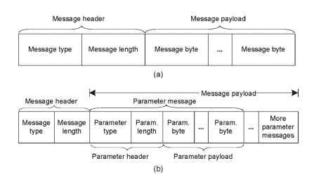
The SDMF contains the calling number, date, and time. A message in SDMF includes a message type byte, a message length byte, and the actual message bytes as shown in Fig. 8.4(a). The MDMF supports multiple messages such as calling number, caller name, date and time, and other optional information. A message in MDMF also includes a message type byte, a message length byte, actual message bytes, and a parameter type and parameter length bytes as shown in Fig. 8.4(b). At certain points within these messages, up to 10 mark bits may be inserted to allow for equipment delays in the central office [GR-30-CORE (1998)]. The message type byte defines whether the message is in SDMF or MDMF. The message length byte is the binary representation of the number of bytes in the message, not including the message type, and the checksum bytes. It supports message payload lengths of up to 255 bytes. In MDMF, the parameter type byte identifies the type and format of the parameter message. The parameter length byte contains the binary representation of the number of bytes contained within the parameter message, excluding the parameter header. The maximum length of the parameter payload is 253 bytes since the maximum message length is 255 bytes, of which the parameters header consumes 2 bytes. The parameter type byte has its unique value for

Figure 8.4. Presentation layer data formats. (a) SDMF. (b) MDMF (note: The Param. acronym is used for Parameters in the diagram).
each feature in MDMF. Refer to the ETSI or Telcordia recommendations for more details on various parameter type code words.
8.2.4
Application Layer
The application layer is where the actual caller ID service is provided. This layer determines the actual content of the data sent to the presentation layer, to suit the information to send to the TE. The application layer is country-dependent and varies between ETSI and Telcordia as well as other specification’s that perform all the necessary interpretation of the data being transported, select the method caller ID display, and provide necessary timing information that is largely dependent on the specific country.
