Running the analysis
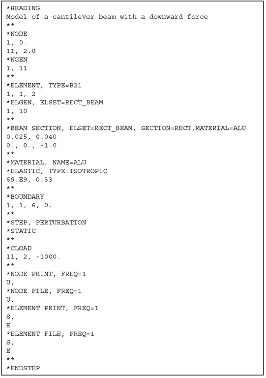
So the whole input file defining the problem of the cantilever beam is shown below:
ABAQUS input files end with the extension .inp. So if we call this file beam.inp, we can run this example in ABAQUS using the following command at the command prompt (note that, to-date, ABAQUS is usually run on a unix platform):
abaqus job = beam
Users can check the full syntax of the ABAQUS execution command in the manuals.
Results
After executing the analysis, there could be several results files generated. In ASCII text format would be the beam.dat file. ABAQUS ouputs its results in ASCII format in the file ending with the extension .dat. As mentioned, the binary format would be in the file with the .fil extension, and is generally used as input for post-processors. The .dat file can of course be viewed by any text editor, and it will show lots of numbers associated with the input processing, the analysis steps, and lastly, the requested outputs (*NODE PRINT and *EL PRINT). These output data can of course be used for plotting graphs or as inputs to other programming codes, depending on the user. Many users would view the results using post-processors like ABAQUS/Post, ABAQUS/Viewer, PATRAN, and so on. The choice is entirely up to the preference of the user, and of course, the availability of these post-processors. In this topic, the results are viewed using PATRAN, and the results are shown below.
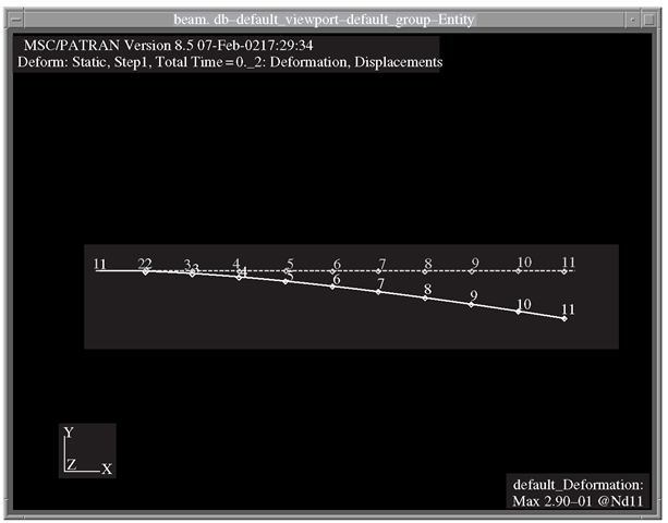
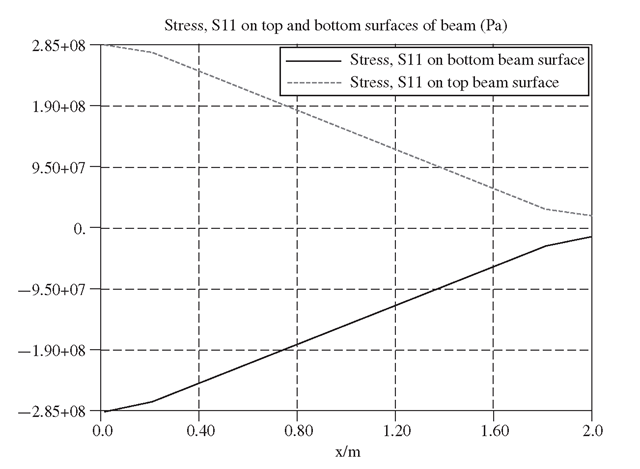
Figure 13.3 shows the deformation plot of the cantilever beam as obtained in PATRAN. This plot shows how the cantilever beam deforms under the applied loads. The actual displacements of the nodes can also be included in the deformation plot, but if there are many nodes, it makes viewing them on-screen difficult. Figure 13.4 shows an XY-plot obtained in PATRAN of the stress, σχχ, on the top and bottom surface of the beam. The plot clearly shows a tensile stress on the top and a compressive stress at the bottom. XY-plots of strain and displacements can be similarly obtained in PATRAN.
Figure 13.3. Deformation plot from PATRAN.
Figure 13.4. XY-plot of stress, σχχ along the beam.
General Procedures
How to write the ABAQUS input file of a simple problem of a cantilever beam has been shown in the previous section. This topic will not be sufficient to go through the many keywords that are available in ABAQUS, and therefore the focus will not concentrate on that. Readers and users should consult the manuals for more information regarding the keywords. This section thus aims to provide a general guide not just to using ABAQUS, but generally to most finite element software.
From the previous example, it can be seen that certain information must be provided for the software to carry out the analysis. This information is required to solve for the finite element problem, and it has been highlighted throughout this topic that the information is mainly used to formulate the necessary matrices. Of course, there are certain parameters that govern the algorithm and the way in which the equations are solved in the program as well. So in this sense, there should not be much difference between different software other than the format in which the information is supplied and the way in which results are presented.
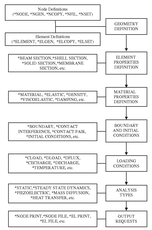
Figure 13.5. General information required by finite element software.
Figure 13.5 is a summary of the general information that finite element software requires to solve most problems. The keywords provided on the left are some of the keywords used in ABAQUS to provide that particular information. To summarize, we would first need to define the geometry by defining the nodes and the elements. Remember that in the finite element method, the whole domain is discretized to small elements. This is generally called meshing. Next, we would need to provide some properties for the elements used. For example, using 1D beam elements would require one to provide the type of crosssection and the cross-section dimension; or when using 2D plate elements it would require the thickness of the plate to be provided, and so on. After that we would need to define the properties of the material or materials being used and associated with the elements. We would then need to provide information regarding the boundary and initial conditions the model is under. This is necessary for the solver to evaluate the equations. Similarly for the loading conditions, which must also be provided unless there is no load on the model like in many analyses involving natural frequencies extraction. After all this, the model is more or less defined. The next step would be to tell the software what type of problem or analysis this is. Is the problem a static analysis, or a transient dynamic analysis, or a heat transfer analysis? The software would require this information and the user must provide it with the analysis type. Finally, the user can also tell the software what are the results he or she is seeking. For example, for most applied mechanics problems, the displacements are the true nodal variables that the solver will compute. The software, however, can also compute the stress and strain from interpolation of these nodal displacements automatically, and this can be done by specifying them in the input file.


