Crack Tip Elements
In fracture mechanics, much interest for analysts is on the tip of the crack, as it is a singularity point where the stress field becomes mathematically infinite. When modelled with the conventional, polynomial-based finite elements discussed in previous topics, the finite element approximations are usually quite bad unless a very dense mesh consisting of numerous small elements is modelled around the crack tip. This may not prove feasible at times, and is highly inefficient when computational resources are limited. It will be a better option to model such a problem with what is known as crack tip elements, sometimes known as singularity elements. Such an element was introduced at almost the same time by Henshell and Shaw [1975] and Barsoum [1976, 1977].
From theories of linear elastic fracture mechanics, the stresses near the crack tip are characterized by the stress intensity factor, Kj ,in Mode I fracture as
and the displacement near the crack tip is expressed as
where G is the shear modulus, and κ = 3 – 4υ (plane strain) or (:3 – υ)/(1+υ) (plane stress). Mode I fracture is considered to be the opening of the crack, as shown in Figure 10.1, and r and θ are as shown. From Eqs. (10.1) and (10.2), it can be seen that the stress varies inversely with φ and the displacement varies proportionally with φ. Note the presence of singularity of the stresses at the crack tip itself when r approaches zero.
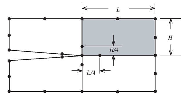
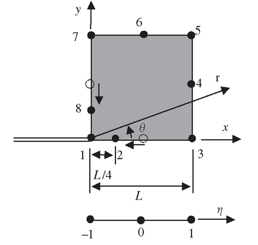
To approximate the behaviour of the stresses and displacements near the crack tip according to the theories of fracture mechanics, a special eight-nodel, quadratic, isoparametric element as shown in Figure 10.2 can be formulated. This element is exactly the same as the usual eight-nodel isoperimetric quadratic element, except that the middle modes on the edges to the crack tip are moved by a quarter of the edge length towards the crack tip. The following explains how the stress singularity is created by this simple modification.
Consider the element side joining nodes 1, 2 and 3 of the isoparametric quadratic element, as shown in Figure 10.3. Following formulation of the conventional eight-node element, the coordinate x and displacement u are both interpolated by shape functions as follows:
Figure 10.1. Mode I crack opening deformation.
Figure 10.2. Modelling of crack tip with crack tip elements.
Figure 10.3. Eight-node, isoparametric, quadratic crack tip element.
Let both x and u be measured from node 1, and let the mid-side node 2 be moved to the quarter-point node 2. For a side of length L, we have
Substitution of Eq. (10.5) into Eqs. (10.3) and (10.4) leads to
Simplifying the above equations will give us
Now, we know that along the x-axis, x = r. Therefore,
Substitution of Eq. (10.10) into Eq. (10.9) leads to
Notice that by shifting the middle node to the quarter position, the displacement now follows a behaviour that is proportional to φ. Furthermore, the strain is given by
where from Eqs. (10.8) and (10.10),
Thus, by using Eqs. (10.9), (10.12) and (10.13),
It is noted that the strain given by Eq. (10.14) is inversely proportional to φ, and since the stress is directly proportional to the strain, this can also be said for the stress. Therefore, it can be seen that by shifting the middle node, 2, to the quarter position, we are able to obtain an approximation that follows the behaviour of the stresses and displacements near the crack tip, as predicted by fracture mechanics. Similar procedures can be applied to the other side consisting of nodes 1, 7 and 8.
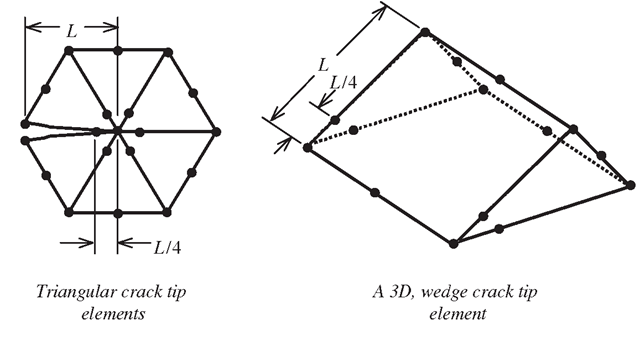
Other types of crack tip elements with different shapes can also be obtained, and some examples are shown in Figure 10.4.
Methods For Infinite Domains
There are many problems in real life that actually involve an infinite or semi-infinite domain. For example, the radiation of heat from a point source into space, and the propagation of waves on the surface of the ground and under the ocean, and so on. For the above problems, the strength of the heat radiation and the amplitude of the waves vanish at infinity. So far, the finite element method we have discussed in this topic all comes with a finite boundary.
Figure 10.4. Examples of crack tip elements.
In fact, all elements introduced are with closed boundaries. Therefore, if these elements are used to model an infinite domain, then the boundary will affect the results obtained. For the propagation of waves, any finite boundary will reflect the waves, and this will result in the superposition of the transmitted and reflected waves. Similarly, for other problems, approximations using conventional finite elements will thus be inaccurate. Intuitively, one might think that one solution to modelling the infinite or semi-infinite domain is to place the finite boundary far away from the area of interest. The question of ‘how far’ is far enough will then set in, and besides, this method would usually require an excessively large number of elements to model regions that the analyst has little interest in. To overcome such difficulties caused by an infinite or semi-infinite domain, many methods have been proposed, of which one of the most effective and efficient is the use of infinite elements.
Infinite Element Formulated by Mapping (Bettess, 1992)
An infinite element is created by using shape functions to approximate a sequence of the decaying form:
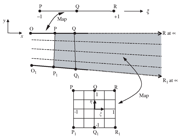
where Ci are arbitrary constants and r is the radial distance from the origin or pole, which can be arbitrarily fixed. Consider the 1D mapping of the line OPQ, which coincides with the x-axis, as shown in Figure 10.5. Like the finite element formulation for all isoparametric elements, the coordinates are interpolated from the nodal coordinates, thus let us propose that
From Eq. (10.16), it can be observed that![]() __ corresponds to
__ corresponds to![]() corresponds to
corresponds to As mentioned, r is the
distance measured from the origin or pole, and we assume that the pole is at O. Therefore,
Solving Eq. (10.16) for ξ would give
Figure 10.5. Infinite line and 2D element mapping.
If the unknown variable, say u, is approximated by a polynomial function such as
then substituting Eq. (10.18) into (10.19) would give us a series of the form given in Eq. (10.15), with the linear shape function in ξ corresponding to 1/r terms, the quadratic shape function to 1 /r2, and so on.
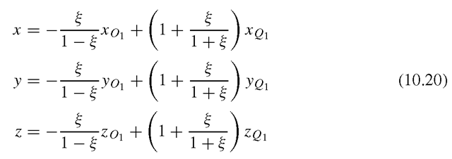
A generalization to 2D or 3D can be achieved by simple products of the 1D, infinite mapping shown above, with a standard type of shape function in η (and ζ for 3D) direction in the manner shown in Figure 10.5. First, we generalize the interpolation of Eq. (10.16) for any straight line in the x, y and z space:
Then we complete the interpolation and map the whole domain of ξη(ζ) by adding a standard interpolation in the η(ζ) directions. Thus, we can write for element PP1QQ1RR1 of Figure 10.5
with
and map the points as shown. In a similar manner, quadratic interpolations could also be used. These infinite elements can be joined to a standard finite element mesh as shown in Figure 10.6.
Figure 10.6. Infinite elements attached to standard finite element mesh.
Gradual Damping Elements
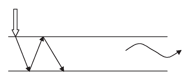
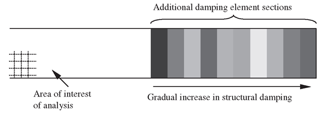
Using elements with gradually increased artificial damping elements attached on the regular finite element mesh is a very efficient way to model vibration problems with infinite boundaries.While on the topic of modelling for an infinite domain, it is our intention to demonstrate that there are certain situations where infinite approximations are not easily achieved. One such application is in the study of lamb wave propagation in infinite plates or beams. Lamb waves are dispersive waves that involve multiple characteristic reflections with the top and bottom surface of the plate as it progresses along the plate, as shown in Figure 10.7. Such waves are actually very much more complex than the usual plane or transverse waves. There are, of course, many numerical methods and analytical methods available to solve such problems. The strip element method, introduced at the end of this topic, can be used effectively for such problems. However, there is the restriction of meshing for irregular geometry, since it involves strip elements. The finite element method is still one of the most versatile methods available for any kind of geometry and applications. The problem is the modelling of the infinite domain for studying the propagation characteristics without interference from reflected waves. It has been proposed to use a gradual damping method to model an infinite plate for such a purpose. This method uses conventional finite elements, and the infinite domain is approximated by adding additional elements with a gradual increase in damping to damp down the amplitude of the propagating waves. Sets of finite elements are attached outside the area of interest of the analyst, as shown in Figure 10.8. The following is a brief description of the method.
Figure 10.7. Dispersive characteristic of lamb wave propagation.
Figure 10.8. Damping element sets attached outside area of interest.
Structural damping is considered in the formulation to represent the internal damping of the material as well as in the artificial boundary so as to damp down the wave oscillations. The energy dissipated in one cycle of an oscillation by a viscous damping force is directly proportional to the frequency of the oscillation and the square of the amplitude of vibration, given by
where ω is the angular frequency and c is the damping coefficient. However, the energy dissipated per cycle is independent of the frequency over a wide frequency range for most structural metals. Therefore, we can let
where H is a damping function, such that the energy dissipated is independent of the angular frequency. The equation of motion for the plate with damping under a harmonic load can then be written as
where c is the global matrix of damping coefficients. To create an artificial boundary to damp down the oscillations, a section of elements (outside the area of interest of the analyst) near the finite boundary is first divided into n element sets. The damping coefficient, and hence the damping force defined for each of these sets, is gradually increased from the innermost set to the set next to the finite boundary. For a harmonic force,
Therefore, Eq. (10.25) can be written as
The complex matrix [k + iH] is known as the complex stiffness, and can be obtained by replacing Young’s modulus E by a complex one, E(1 + ia), where a is the material loss factor. By doing so, the complex stiffness matrix can be expressed as
Hence, from Eqs. (10.28) and (10.24),
To gradually increase this damping force, Young’s modulus for the kth damping element set added beyond the area of interest can be expressed as
where α0 can be regarded as the initial material loss factor for the artificial damping boundary, and ζ is a constant factor.
This exponential function ensures that the rate of increase in damping is low at the beginning and becomes higher as k increases. This will prevent a sudden increase in the damping that will itself cause reflection of the propagating wave. To determine the value of ζ, which is required to provide sufficient damping, an iterative procedure of increasing ζ is used until the responses obtained for two (or more) cases of different boundary conditions at the ends show no significant differences. This is based on the concept that the damping has done its job such that the effects of the boundary are no longer significant. Hence, the two criteria for achieving the required damping are
1. Sufficient damping such that the effect of the boundary is negligible.
2. Damping is gradual enough such that there is no reflection caused by a sudden damped condition.
This method has been shown to give good approximations for wave propagations in an infinite domain, and the main advantage is the versatility of the finite element method for meshing any complex or irregular geometry. The method can be easily applied using most of the commercial software packages.


