Modelling of Joints
Care should be taken if the joints are between different element types. The complication comes from the difference in DOFs at a node in different elements. In many situations, a proper technique or a set of MPC equations is required to model the connection.
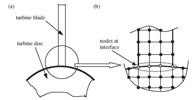
Consider a connection between the turbine blade and the turbine disc shown in Figure 11.35(a). A turbine blade is usually perfectly connected to a disc. We now need to build a FEM model to analyse the blade-disc system. If both the blade and disc are all modelled using 2D solid elements, as shown in Figure 11.35(b), the perfect connection is ensured as long as we perform a nodal equivalence operation so that at the interface the blade and disc share the same nodes.
Figure 11.35. Modelling of turbine-blade and turbine-disc system. (a) Simplified diagram of a turbine blade connected to a turbine disc; (b) a magnified 2D solid element mesh at the interface.
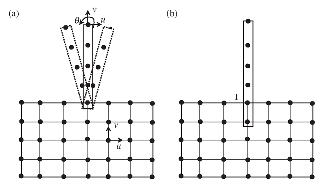
Figure 11.36. Joint between beam and 2D elements. (a) Beam is free to rotate in reference to the 2D solid; (b) perfect connection modelled by artificially extending the beam into a 2D element mesh.
Assume an FEM model where the blade is modelled using beam elements, and the disc is modelled using 2D elements, as shown in Figure 11.36. This model clearly reduces the number of nodes, and thus the DOFs. However, one needs to use a proper technique to model the connection properly, for the reasons given below.
First, we consider the connection of the beam element and 2D solid elements in the way shown in Figure 11.36(a). From Table 11.1, we know that at a node in a 2D solid element there are two DOFs: the translational displacement components u and v. At a node in a beam element, there should be three DOFs: two translational displacement components u and v, and one rotational DOF. Although the beam element and the 2D elements share the common node 1, which ensures that the translational displacements are the same at the connection point for the beam and 2D solid, the rotation DOF at the beam element is, however, free. Therefore, the blade can rotate freely in reference to the 2D solid, which is not the perfect connection we wanted to model. The problem is the mismatch of the types of DOFs between the beam and 2D solid elements. The rotational DOF cannot be transmitted onto the node on a 2D solid element node, simply because it does not have rotational DOF. Modelling techniques are therefore required to fix this problem.
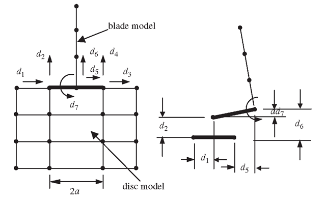
Figure 11.37. Modelling of the turbine blade connected to the disc using a rigid strip to create MPC equations.
A simple method to fix the rotation of the beam on the 2D solid mesh is to extend the beam elements (artificially) into the disc for at least two nodes, as shown in Figure 11.36(b). This allows transmission of both translational and rotation deformation between the beam and 2D elements. The drawback of this simple method is the additional mass introduced near the joint area, which may affect the results of a dynamic analysis.
Another effective method is to use MPC equations to create a connection between the two types of elements. The detailed process is given as follows. First, assume that there is a very thin rigid strip connecting the beam and the disc, as shown in Figure 11.37. This strip connects three nodes together, one on the beam and two on the disc. These three nodes have to move together with the rigid strip. The MPC equations can then be established in a manner similar to that discussed for offsets.
Note that a node on the beam has three DOFs, whereas the two nodes on the disc have a total of four DOFs. The total number of DOFs connected to the rigid strip is thus seven. Since the DOF of the rigid strip is three, we should have four MPC equations following Eq. (11.8). The four MPC equations are given as:
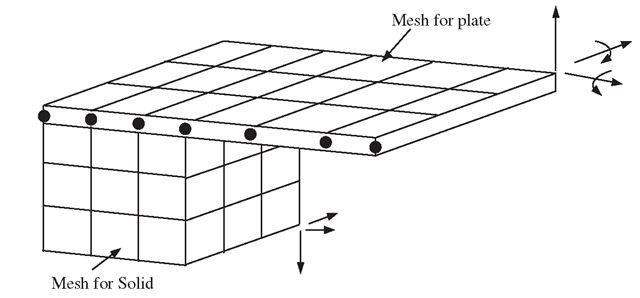
Figure 11.38. Joint between plate and 3D solids modelled by extending plate into a 3D solid element mesh.
These equations enforce full compatibility between the beam and the disc.
A similar problem can occur on the connection between the plate or shell elements that posses rotational DOFs with 3D solid elements that do not possess a rotational DOF. Such a connection between a plate and a 3D solid can be similarly modelled using this method, as shown in Figure 11.38.
Other Applications of MPC Equations
Modelling of Symmetric Boundary Conditions
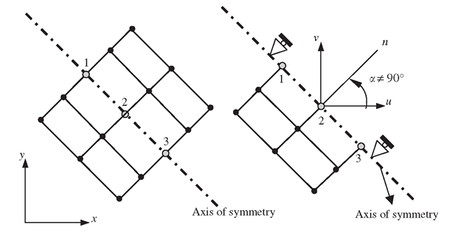
When discussing the modelling of symmetric problems, it was mentioned that constraint (boundary) equations are required to ensure that symmetry is properly defined. Note that Eq. (11.2) was obtained when the axis of symmetry is parallel (or perpendicular) to an axis of the Cartesian coordinates. When the axis of symmetry is not parallel (or perpendicular) to the x- or y-axis, as shown in Figure 11.39, the displacement in the normal direction of the axis of symmetry should be zero, i.e.
which implies
where Ui and Vi denote the x and y components of displacement at node i .Equation (11.12) is an MPC equation as it involves more than one DOF (Ui and Vi ). When a = 0, the axis of symmetry is parallel to the y-axis, and Eq. (11.12) will reduce to a SPC that is Eq. (11.2).
Enforcement of Mesh Compatibility
Section 11.5.1 discussed mesh compatibility issues, and it was mentioned that to ensure mesh compatibility on the interface of different types of elements, we can make use of MPC equations.
Figure 11.39. Imposing mirror symmetry using MPC when the axis of symmetry is not parallel (or perpendicular) to the x- or y-axes.
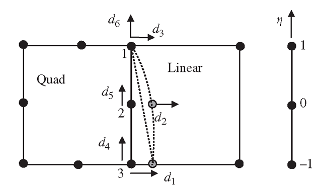
Figure 11.40. Enforcing compatibility of two elements of different orders using MPC.
We now detail the procedure. With reference to Figure 11.40, the procedure of deriving the MPC equations is as follows:
• Use the lower order shape functions to interpolate the displacements on the edge of the element. In this example, the linear shape functions are used, which gives the displacement at any point on the edge 1-3 as
• Next, substitute the value of η at node 2 into the above two equations to get the constraint equations:
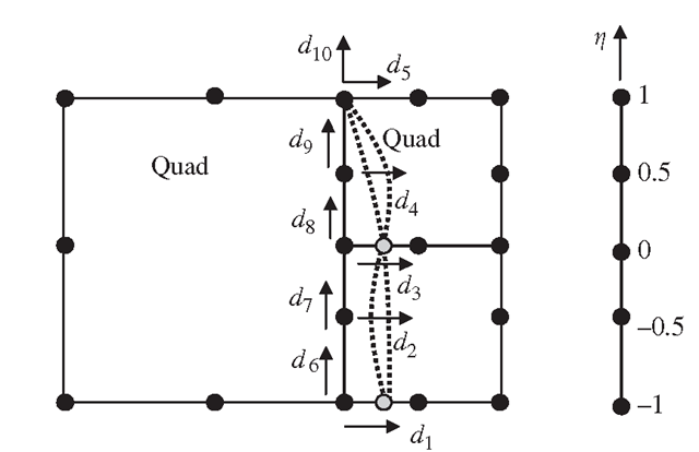
Figure 11.41. Enforcingthecompatibilityoftwodifferentnumbersofelementsonacommonedge using MPC.
These are the two MPC equations for enforcing compatibility on the interface between two different types of elements.
When it is not possible to have gradual mesh density transition and a number of elements share a common edge, as shown in Figure 11.41, mesh compatibility can also be enforced by MPC equations. The procedure is given as follows:
• Use the shape functions of the longer element to interpolate the displacements. Then, for the DOF in the x direction, the quadratic shape function gives
• Substituting the values of η for the two additional nodes of the elements with shorter edges yields
Which can be simplified to the following two constraint equations in the x-direction:
Similarly, the constraint equations for the displacement in the y direction are obtained as
Equations (11.20)-(11.23) are a set of MPC equations for enforcing compatibility of the interface between different numbers of elements.
Modelling of Constraints by Rigid Body Attachment
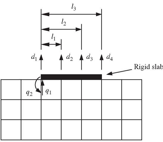
A rigid body attached on an elastic body will impose constraints on it. Figure 11.42 shows a rigid slab sitting on an elastic foundation. Assume that the rigid slab constrains only the vertical movement of the foundation, and it can move freely in the horizontal direction without affecting the foundation. To simulate such an effect of the rigid slab sitting on the foundation, MPC equations are required to enforce the four vertical DOFs on the foundation to follow the two DOFs on the slab.
First, the four equations are:
where qi and q2 are, respectively, the translation and rotation of the rigid slab. Then, eliminating the DOFs of the rigid body q1 and q2 from the above four equations leads to two MPC equations:
In the above example, the DOF in the x -direction was not considered, because it is assumed that the slab can move freely in the horizontal direction, and hence it will not provide any constraint to the foundation. If the rigid slab is perfectly connected to the foundation, the constraints on the DOFs in the x-direction must also be considered.
Figure 11.42. Modelling of a rigid slab on an elastic foundation using MPC.
![tmp5896-242_thumb[2][2][2] tmp5896-242_thumb[2][2][2]](http://what-when-how.com/wp-content/uploads/2012/06/tmp5896242_thumb222_thumb.png)
![tmp5896-248_thumb[2][2][2] tmp5896-248_thumb[2][2][2]](http://what-when-how.com/wp-content/uploads/2012/06/tmp5896248_thumb222_thumb.png)
![tmp5896-249_thumb[2][2][2] tmp5896-249_thumb[2][2][2]](http://what-when-how.com/wp-content/uploads/2012/06/tmp5896249_thumb222_thumb.png)
![tmp5896-252_thumb[2][2][2] tmp5896-252_thumb[2][2][2]](http://what-when-how.com/wp-content/uploads/2012/06/tmp5896252_thumb222_thumb.png)
![tmp5896-253_thumb[2][2][2] tmp5896-253_thumb[2][2][2]](http://what-when-how.com/wp-content/uploads/2012/06/tmp5896253_thumb222_thumb.png)
![tmp5896-254_thumb[2][2][2] tmp5896-254_thumb[2][2][2]](http://what-when-how.com/wp-content/uploads/2012/06/tmp5896254_thumb222_thumb.png)
![tmp5896-255_thumb[2][2][2] tmp5896-255_thumb[2][2][2]](http://what-when-how.com/wp-content/uploads/2012/06/tmp5896255_thumb222_thumb.png)
![tmp5896-256_thumb[2][2][2] tmp5896-256_thumb[2][2][2]](http://what-when-how.com/wp-content/uploads/2012/06/tmp5896256_thumb222_thumb.png)
