Cyclic Symmetry
Cyclic symmetry prevails in problems where both geometry and loading appear as repeated sectors. In such a case, a complete solution can be obtained by analysing only one sector as a representative cell with a set of cyclic boundary conditions on the boundaries of the cell, as shown in Figure 11.25. The cyclic symmetric boundary condition for the problem shown in Figure 11.25 should be that all the variables along side A must match exactly those on side B. Constraint equations at all the corresponding nodes along sides A and B can therefore be written as
Note that in Eqs. (11.3) and (11.4), both uAn and uBn (or uAt and uBt) are unknowns. Thus, Eqs. (11.3) and (11.4) are constraint equations that involve more than one DOF in one equation. These types of constraint equations are termed Multi-Point Constraint (MPC) equations, which have to be imposed by modifying the global system equations.In the imposition of SPC, all one need do is remove (or modify) the corresponding rows and column in the system equations (see Examples 4.1 and 4.2). The imposition of MPC requires the use of either penalty method or the method of Lagrange multipliers, that are detailed in Section 11.11.
Repetitive Symmetry
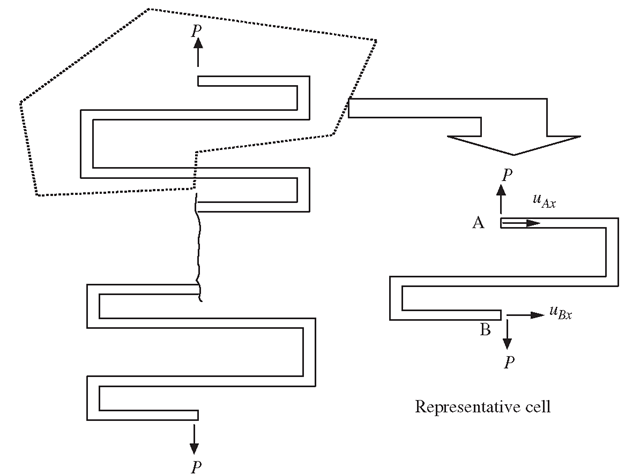
Repetitive symmetry prevails in structures consisting of continuously repeating sections under certain loading conditions (usually in the direction of a repeating section), as shown in Figure 11.26. In such a case, only one section needs to be modelled and analysed. Similar to cyclic symmetry, constraint equations are used for the corresponding nodes at the sectioned surface, such that
which is again an MPC equation.
Figure 11.26. Representative cell isolated from a repetitive symmetric structure and the repetitive symmetrical conditions on the cell.
Modelling of Offsets
Methods for Modelling Offsets
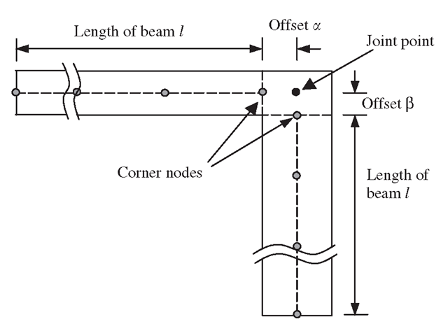
In the modelling of beams, plates and shells, the elements are usually defined on the neutral surface (often the geometric middle surface) of the structure, as shown in Figure 11.3. For elements that are not collinear or coplanar, there will be a distance of offset between the nodes in the FEM mode, which are connected together in the physical structure. Figure 11.27 shows a typical case of two beams with different thickness joined at the corner. In the finite element mesh, however, the two corner nodes are apart. In this case, there are two offsets, a and β. In such cases, proper techniques may be a need to model the offset in order to simulate the actual connected situation.
If the offsets are too small compared to the length of the beam l, we can often ignore it, and the connection is simply modelled by extending the corner nodes to the joint point (see Figure 11.27). If the offsets are too large, it has to be treated using proper modelling techniques. Whether offsets should be modelled depends upon the engineering judgment of the analyst.
Figure 11.27. Offsets at the joint of two beams with different thickness.
A rough guideline shown below can be followed where l is the length of the beam:
1. a < 1/100, offset can be safely ignored
2. 1/100 < a <l/5, offset needs to be modelled
3. a > l/5, ordinary beam, plate and shell elements should not be used. Use 2D or 3D solid elements.
Modelling of offsets is usually even more crucial in shells as there are both in-plane and out-of-plane forces in the formulation, and a small variation of nodal distance can give rise to a significant difference in results. There are three methods often used to model the offsets:
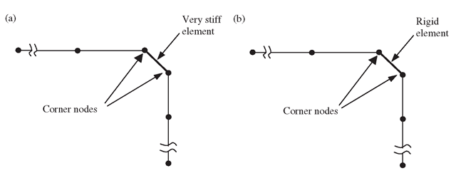
1. Very stiff element. Use an artificial element with very high stiffness (high Young’s modulus, large cross-sectional area or second moment of area) to connect the two corner nodes (see Figure 11.28(a)). This is usually done by increasing the Young’s modulus by, say, 106 times for the very stiff element. This method is very simple and convenient to use, but is usually not recommended because too large a difference in stiffness among the elements in the same FE model can lead to ill-conditioning of the final set of global stiffness matrices.
2. Rigid element. Use an artificial element with a property of a ‘rigid element’ to connect the corner nodes (see Figure 11.28(b)). This method is good, and is available in many commercial software packages; all the analyst needs to do is create an element in between the two corner nodes and then assign it as a ‘rigid element’. The treatment of the rigid element in the software package is the same as the next method using MPC equations, but the formulation and implementation is automated in the software package, so the user does not have to formulate these MPC equations.
Figure 11.28. Modelling of offsets using an artificial element connecting the two corner nodes. (a) Use of very stiff element; (b) use of rigid element.
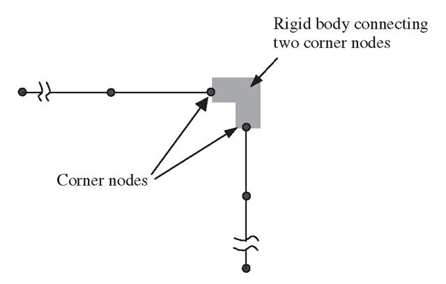
Figure 11.29. Modelling of offsets using MPC equations created using a‘rigid body’ connecting two corner nodes.
3. MPC equations. If the ‘rigid element’ is not available in the software package, we then need to create multipoint constraints (MPC) equations to establish the relationship between the DOFs at the two corner nodes. This set of MPC equations is then input in the preprocessor. Use of MPC equations is supported by most FEM software packages. The MPC equations can be created using an artificial rigid body that connects these two corner nodes, as shown in Figure 11.29. The detailed process is discussed in the next subsection.
Creation of MPC Equations for Offsets
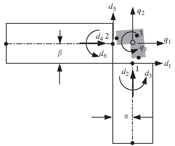
The basic idea of using MPC is to create a set of MPC equations that gives the relation between the DOFs of the two separated nodes. It assumes that the two corner nodes are connected by a rigid body. MPC equations are then derived using the simple kinematic relations of the DOFs on the rigid body. The procedure of deriving the MPC equations for the case in Figure 11.30 is described as follows.
Figure 11.30. A rigid body is used for deriving the MPC equations.
First, assume that nodes 1 and 2 are perfectly connected to the rigid body, and that the rigid body has a movement of q1, q2 and q3 with reference to point 3, as shown in Figure 11.30. Then, enforce points 1 and 2 to follow the rigid body movement, and calculate the resultant displacements at nodes 1 and 2 in terms of qi, q2 and q3, to obtain
Finally, eliminating the DOFs for the rigid body q1,q2 and q3 from the above six equations, we obtain three MPC equations:
which gives the relationship between the six DOFs at nodes 1 and 2.
The number of MPC equations one should have can be determined by the following equation:
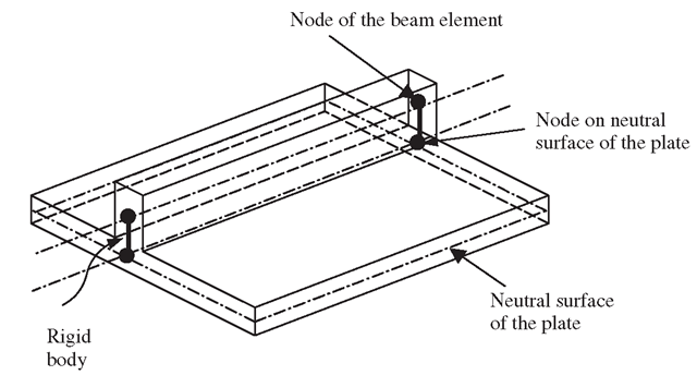
Another example of an offset is often seen in structures called stiffened plates and shells, where a beam is fixed to a plate as a stiffener, as shown in Figure 11.31. In this case, the offset should be modelled if accurate results are required.
Figure 11.31. Stiffened plates with an offset in between the axis of a beam and mid-surface of a plate.
Figure 11.32. DOFs at nodes in the plate and beam.
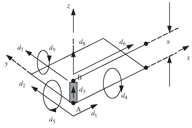
The offset can be modelled by assuming that the node on the beam is connected to the corresponding node at the plate by a rigid body A-B. For a node in the plate, there are five DOFs (three translational and two rotational about the two axes in the plane of the plate), as shown in Figure 11.32. For a node in the beam there are four DOFs (three translational and one rotational about the axis perpendicular to the bending plane). Note that, in this case, the beam has been defined with its bending plane as the x-z plane. Hence, there are a total of nine DOFs connected by the rigid body linking the node on the beam and the node on the plate. To simplify the process of deriving MPC equations, we let the rigid body follow the movement of node A in the plate. Therefore, the rigid body should have the same number of DOFs as the node in the plate, which is 5. The number of MPC equations should therefore be 9 – 5 = 4, following Eq. (11.8). As the rigid body follows the movement of A in the plate, what should be done is to force the node belonging to the beam to follow the movement of B on the rigid body.
The resulting four constraint equations should be
The above equations must be specified as constraints for all pairs of nodes along the length of the beam attached on the plate. This ensures that the beam is perfectly attached onto the plate.
Modelling of Supports
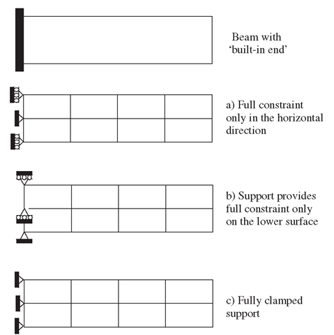
Support of a structure is usually very complex. The FEM allows the constraint to be imposed differently at different nodes. Different methods can be used to simulate these supports. For example, in the analysis of thick beam structures using 2D plane stress elements, there are three possible ways to model the support conditions at the built-in end, as shown in Figure 11.33:
1. Full constraint is imposed at the boundary nodes only in the horizontal direction.
2. Partial full constraint to the nodes on the boundary.
3. Fully clamped boundary conditions are specified at all the boundary nodes.
Figure 11.33. Modelling of built-in end support of beam.
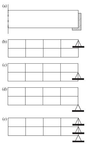
Figure 11.34. Modelling of prop support for a beam.
It is not possible to say which method is the best, because it is actually that which best simulates the situation. Therefore, good engineering judgment, experience and an understanding of the actual situation of support play important roles in creating a good finite element model. Similarly, for a prop support of a beam, there can be more than one way of modelling the support conditions shown in Figure 11.34.
For complex support on structures, it might be necessary to use finer meshes near the boundary. Denser nodes provide more flexibility to model the support, as the FEM allows specification of different constraints at different nodes.
![tmp5896-224_thumb[2][2] tmp5896-224_thumb[2][2]](http://what-when-how.com/wp-content/uploads/2012/06/tmp5896224_thumb22_thumb.png)
![tmp5896-226_thumb[2][2] tmp5896-226_thumb[2][2]](http://what-when-how.com/wp-content/uploads/2012/06/tmp5896226_thumb22_thumb.png)
![tmp5896-231_thumb[2][2] tmp5896-231_thumb[2][2]](http://what-when-how.com/wp-content/uploads/2012/06/tmp5896231_thumb22_thumb.png)
![tmp5896-232_thumb[2][2] tmp5896-232_thumb[2][2]](http://what-when-how.com/wp-content/uploads/2012/06/tmp5896232_thumb22_thumb.png)
![tmp5896-233_thumb[2][2] tmp5896-233_thumb[2][2]](http://what-when-how.com/wp-content/uploads/2012/06/tmp5896233_thumb22_thumb.png)
![tmp5896-236_thumb[2][2] tmp5896-236_thumb[2][2]](http://what-when-how.com/wp-content/uploads/2012/06/tmp5896236_thumb22_thumb.png)
