Elements With Curved Edges
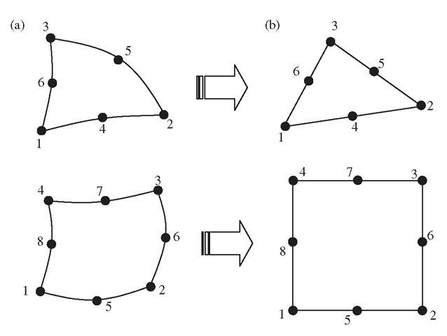
Using high order elements, elements with curved edges can be used in the modelling. Two relatively frequently used higher order elements of curved edges are shown in Figure 7.20(a). In formulating these types of elements, the same mapping technique used for the linear quadrilateral elements (Section 7.4) can be used. In the physical coordinate system, elements with curved edges, as shown in Figure 7.20(a), are first formed in the problem domain. These elements are then mapped into the natural coordinate system using Eq. (7.67). The elements mapped in the natural coordinate system will have straight edges, as shown in Figure 7.20(b).
Figure 7.20. 2D solid elements with curved edges. (a) Curved elements in the physical coordinate system. (b) elements with straight edges obtained by mapping.
Higher order elements of curved edges are often used for modelling curved boundaries. Note that elements with excessively curved edges may cause problems in the numerical integration. Therefore, more elements should be used where the curvature of the boundary is large. In addition, it is recommended that in the internal portion of the domain, elements with straight edges should be used whenever possible.
Comments on Gauss Integration
When the Gauss integration scheme is used, one has to decide how many Gauss points should be used. Theoretically, for a one-dimensional integral, using m points can give the exact solution for the integral of a polynomial integrand of up to an order of (2m – 1). As a general rule of thumb, more points should be used for a higher order of elements. It is also noted that using a smaller number of Gauss points tends to counteract the over-stiff behaviour associated with the displacement-based finite element method.
This over-stiff behaviour of the displacement-based finite element method comes about primarily because of the use of the shape function. As discussed, the displacement in an element is assumed using shape functions interpolated from the nodal displacements. This implies that the deformation of the element is actually prescribed in the fashion of the shape function. This gives a constraint to the element, and thus the element behaves more stiffly than it should. It is often observed that higher order elements are usually softer than lower order ones. This is because the use of more nodes decreases the constraint on the element.
Coming back to the Gauss integration issue, two Gauss points for linear elements, and about two or three Gauss points in each direction for quadratic elements, should be sufficient for most cases. Many of the explicit FEM codes based on explicit formulation tend to use one-point integration to achieve the best performance in saving CPU time.
Case Study: Side Drive Micro-Motor
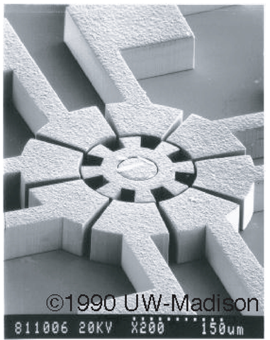
In this case study, we analyse another MEMs device: a common micro-actuator in the form of a side drive electrostatic micro-motor, as shown in Figure 7.21. Such micro-motors are usually made from polysilicon using lithographic techniques. Their diameters vary depending on the design, with the first designs having diameters of 60-120 ^m. Of course, the actual working dynamics of the micro-motor will be rather complex to model, though it can still be readily done if required. Therefore, to illustrate certain points pertaining to the use of basic 2D solid elements, we basically use the geometrical and material information for this micro-motor and apply arbitrary loading and boundary conditions to it.
Isotropic material properties will be employed here to makes things less complicated. The material properties of polysilicon are shown in Table 7.2. We shall do a stress analysis on the rotor with some loading condition on the rotor blades. Examining the rotor in Figure 7.21, we can see that it is symmetrical, i.e. we need not model the full rotor, but rather we can just model say one quarter of the rotor and apply the necessary boundary conditions. We can do this since this one-quarter model will be repeated geometrically anyway. Of course, we can even model one eighth of the model and the results will be the same if the condition of repetition is properly applied. Hence, this becomes a neat and efficient way of modelling repetitive or symmetrical geometry.
Figure 7.21. SEM image of an electrostatic micro-motor with eight rotor and 12 stator poles.
Table 7.2. Elastic properties of polysilicon
|
Young’s Modulus, E |
169 GPa |
|
Poisson’s ratio, ν |
0.262 |
|
Density, ρ |
2300 kgm-3 |
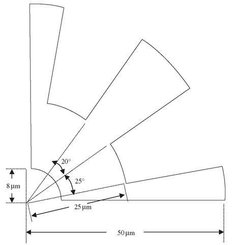
Figure 7.22. Plan view (2D) of a quarter of micro-motor rotor.
Modelling
Figure 7.22 shows the one-quarter model of the micro-motor rotor. We take the diameter of the whole rotor to be 100 ^m and the depth or thickness to be 13 ^m, to correspond with realistic values of micro-motor designs. The geometry can be easily drawn using preprocessors like PATRAN or using basic CAD software, after which it can be imported into preprocessors for meshing.
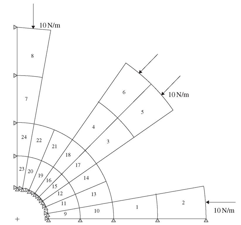
Figure 7.23. Finite element mesh with 24 2D quadrilateral, four nodal elements.
Note that preprocessors are software used to aid us in visualizing the geometry, and to mesh up the geometry using finite elements, especially for complicated geometries. To illustrate the formulation of the finite element equations clearly, we would initially mesh up the geometry in Figure 7.22 with a very sparse mesh, as shown in Figure 7.23. Four nodal, quadrilateral elements are used with a total of 24 elements and 41 nodes in the model. We shall increase the number of elements (and nodes) in later analyses to compare the results. Since the depth or thickness of the motor is much smaller than the other dimensions, and the external forces are assumed to be within the plane of the rotor, we can assume plane stress conditions.
In the above figure, it can also be seen that a distributed force of 10N/m is applied compressively to the rotor blades. The centre hole in the rotor which is supposed to be the location for a ‘hub’ to keep the rotor in place is assumed to be constrained. The nodes along the edge y = 0 are constrained in the y direction and the nodes along the edge x = 0 are constrained in the x direction. These are to simulate the symmetrical boundary conditions of the model, since those nodes are not supposed to move in the direction normal to the plane of symmetry. Similarly, if we are to model a one-eighth model, such rules for symmetry apply except that one of the planes of symmetry will be the line y = x.
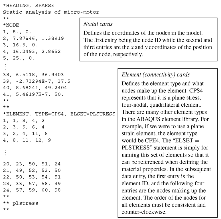
ABAQUS Input File
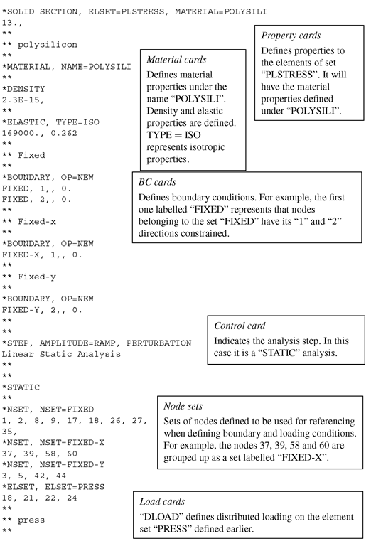
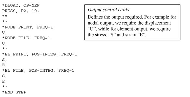
The ABAQUS input file for the above described finite element model is shown below. Note that some parts of the input file containing the data values are left out to limit the length of the file in this topic. The text boxes to the right of the input file are not part of the file, but rather explain what the sections of the file mean.
The input file above shows how a basic ABAQUS input file can be set up. It should be noted that the units used in this case study are micrometres, and all the conversions of the necessary inputs is done for consistency, as before.
