Case Study: Temperature Distribution of Heated Road Surface
Figure 12.20 shows a cross-section of a road with heating cables to prevent the surface of the road from freezing. The cables are 4 cm apart and 2 cm below the surface of the road. The slab rests on a thick layer of insulation, and the heat loss from the bottom can be neglected. The conductivity coefficients are kx = ky = 0.018 W/cm°C and the surface convection coefficient is h = 0.0034 W/cm°C. The latter corresponds to about a 30-35 km/hr of wind velocity. The surface temperature of the road is to be determined when the cable produces 0.080 W/cm of heat, and the air temperature is —6°C.
Modelling
Since the road is very long in the horizontal direction, a representative section shown in Figure 12.20 can be used to model the whole problem domain. The FE mesh is shown in Figure 12.21, together with boundary conditions specified.
The mesh shown in Figure 12.21 demonstrates mesh transition from an area consisting of a sparse mesh to an area of denser mesh. The analyst has chosen to mesh it this way, since the temperature distribution at the bottom of the model is not that critical. Hence, computational time is reduced as a result. The transition is done with the use of triangular elements in between larger rectangular elements and smaller rectangular elements. Note that all the elements used are linear elements, and hence the mixture of elements here is still compatible.
ABAQUS Input File
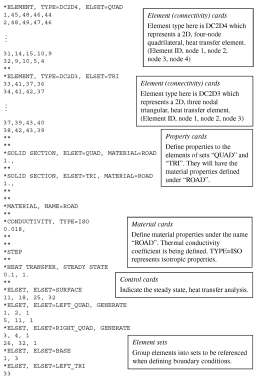
Part of the ABAQUS input file is shown here:
The information provided in the above input file is used by the software in similar ways as discussed in case studies in previous topics.
Result and Discussion
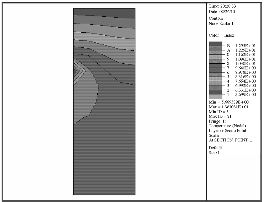
Running the above problem in ABAQUS, the nodal temperatures can be calculated. Figure 12.22 shows a fringe plot of the distribution of the temperatures in the model. It can be seen clearly how the temperature varies from a maximum at the heat source (the heating cables) to other parts of the road cross-section.
In the analysis, the temperatures at all the nodes are calculated. For this problem, we would be interested in only the temperature of the road surface. Table 12.1 shows the nodal temperature on the surface of the road. It can be seen here how the presence of the heating cables under the road is able to keep the road surface at a temperature above the freezing point of water (0°C), as shown in Table 12.1. This would prevent the build up of ice on the road surface during winter, which makes it safer for drivers on the road. The usefulness of the finite element method is demonstrated here, as there are actually many parameters involved when it comes to designing such a system. For example, how deep should the cables be buried underground; what should be the distance between cables; what amount of heat generated by the heating cables is sufficient for the purpose, and so on.
Figure 12.22. Temperature distribution of the cross-section of a road.
Table 12.1. Nodal temperatures of road surface
|
Node |
Temperature (0C) |
|
1 |
5.861 |
|
2 |
5.832 |
|
3 |
5.764 |
|
4 |
5.697 |
|
5 |
5.669 |
The finite element method used here can effectively aid the engineer in deciding upon all these parameters.


