IP Telephony Deployment Models
Each IP Telephony deployment model differs in the type of traffic that is carried over the WAN, the location of the call-processing agent, and the size of the deployment. Cisco IP telephony supports these deployment models:
■ Single site
■ Multisite with centralized call processing
■ Multisite with distributed call processing
■ Clustering over the IP WAN
Single-Site Deployment
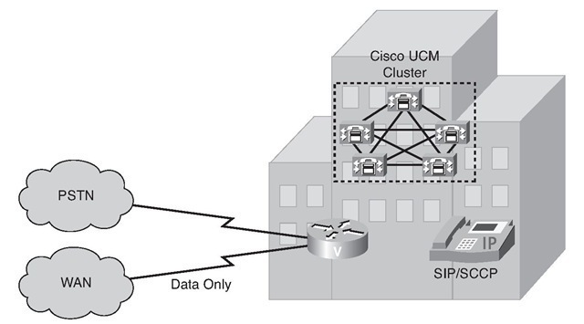
The single-site model for Cisco Unified Communications consists of a call-processing agent cluster located at a single site, or campus, with no telephony services provided over an IP WAN. Figure 1-25 illustrates a typical single-site deployment. All Cisco UCM servers, applications, and DSP resources are located in the same physical location. You can implement multiple clusters inside a LAN or a metropolitan-area network (MAN) and connect them through intercluster trunks if you need to deploy more IP phones in a single-site configuration.
Figure 1-25 Single-Site Deployment
An enterprise typically deploys the single-site model over a LAN or MAN, which carries the voice traffic within the site. Gateway trunks that connect directly to the PSTN handle all external calls. If an IP WAN exists between sites, it is used to carry data traffic only; no telephony services are provided over the WAN.
Design Characteristics of Single-Site Deployment
The single-site model has the following design characteristics:
■ Single Cisco UCM cluster.
■ Maximum of 30,000 SCCP or SIP IP phones or SCCP video endpoints per cluster.
■ Maximum of 1100 H.323 devices (gateways, MCUs, trunks, and clients) or MGCP gateways per UCM cluster.
■ PSTN for all calls outside the site.
■ DSP resources for conferencing, transcoding, and media termination point (MTP).
■ Voicemail, unified messaging, Cisco Unified Presence, audio and video components.
■ Capability to integrate with legacy PBX and voice-mail systems.
■ H.323 clients, MCUs, and H.323/H.320 gateways that require a gatekeeper to place calls must register with a Cisco IOS Gatekeeper (Cisco IOS Release 12.3(8)T or greater). UCM then uses an H.323 trunk to integrate with a gatekeeper and provide call routing and bandwidth management services for H.323 devices registered to it. Multiple Cisco IOS Gatekeepers might be used to provide redundancy.
■ MCU resources are required for multipoint video conferencing. Depending on conferencing requirements, these resources might be either SCCP or H.323, or both.
■ H.323/H.320 video gateways are needed to communicate with H.320 videoconferencing devices on a public ISDN network.
■ High-bandwidth audio (for example, G.711, G.722, or Cisco Wideband Audio) between devices within the site.
■ High-bandwidth video (for example, 384 kbps or greater) between devices within the site. The Cisco Unified Video Advantage Wideband Codec, operating at 7 Mbps, is also supported.
Benefits of Single-Site Deployment
A single infrastructure for a converged network solution provides significant cost benefits and enables Cisco Unified Communications to take advantage of many IP-based applications in an enterprise. Single-site deployment also allows each site to be completely self-contained. There is no dependency for service in the event of an IP WAN failure or insufficient bandwidth, and there is no loss of call processing service or functionality.
The main benefits of the single-site model are the following:
■ Ease of deployment.
■ A common infrastructure for a converged solution.
■ Simplified dial plan.
■ No transcoding resources are required because of the use of a single high-bandwidth codec.
Design Guidelines for Single-Site Deployment
Single-site deployment is a subset of the distributed and centralized call-processing model. Future scalability requires you adhere to the recommended best practices specific to the distributed and centralized call-processing model. When you develop a stable, single site that is based on a common infrastructure philosophy, you can easily expand the IP telephony system applications, such as video streaming and videoconferencing, to remote sites.
Best Practices for Single-Site Deployment Follow these guidelines and best practices when implementing the single-site model:
■ Provide a highly available, fault-tolerant infrastructure based on a common infrastructure philosophy. A sound infrastructure is essential for easier migration to Cisco Unified Communications, integration with applications such as video streaming and video conferencing, and expansion of your Cisco Unified Communications deployment across the WAN or to multiple UCM clusters.
■ Know the calling patterns for your enterprise. Use the single-site model if most of the calls from your enterprise are within the same site or to PSTN users outside your enterprise.
■ Use G.711 codecs for all endpoints. This practice eliminates the consumption of DSP resources for transcoding, and those resources can be allocated to other functions such as conferencing and MTPs.
■ Use SIP, SRST, and MGCP gateways for the PSTN. This practice simplifies dial plan configuration. H.323 might be required to support specific functionality, such as support for SS7 or Non-Facility Associated Signaling (NFAS), which allows a single channel on one digital circuit to carry signaling information for multiple digital circuits.
■ Implement the recommended network infrastructure for high availability, connectivity options for phones (in-line power), QoS mechanisms, and security.
Multisite WAN with Centralized Call-Processing Deployment
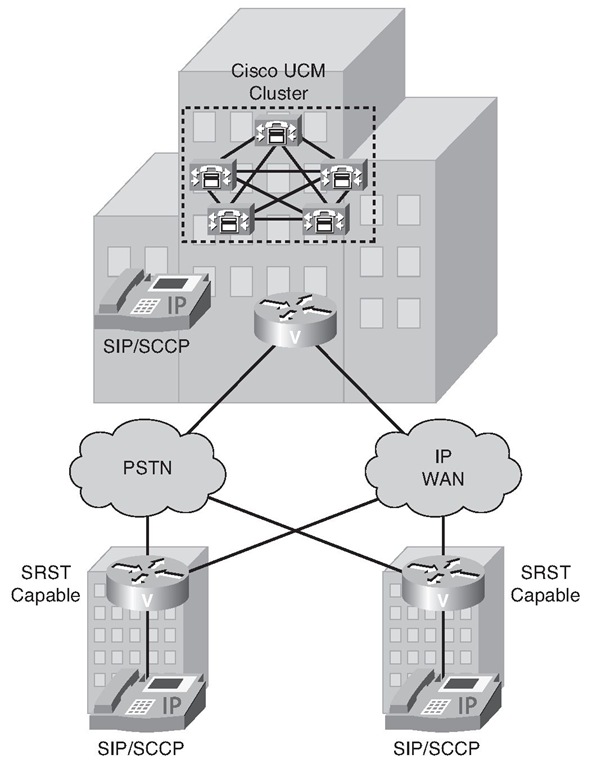
The model for a multisite WAN deployment with centralized call processing consists of a single call-processing agent cluster that provides services for multiple remote sites and uses the IP WAN to transport Cisco Unified Communications traffic between sites. The IP WAN also carries call control signaling between central and remote sites. Figure 1-26 illustrates a typical centralized call processing deployment, with a UCM cluster as the call processing agent at the central site and an IP WAN with QoS enabled to connect all the sites. The remote sites rely on the centralized UCM cluster to handle their call processing. Applications such as voice mail and IVR systems are typically centralized as well to reduce the overall costs of administration and maintenance.
Figure 1-26 Multisite WAN with Centralized Call Processing
WAN connectivity options include the following:
■ Leased lines
■ Frame Relay
■ ATM
■ ATM and Frame Relay Service Inter-Working (SIW)
■ Multiprotocol Label Switching (MPLS) VPN
■ Voice and Video Enabled IP Security Protocol (IPsec) VPN (V3PN)
Routers that reside at WAN edges require QoS mechanisms, such as priority queuing and traffic shaping, to protect voice traffic from data traffic across the WAN, where bandwidth is typically scarce. In addition, a call admission control scheme is needed to avoid oversubscribing the WAN links with voice traffic and deteriorating the quality of established calls. For centralized call-processing deployments, the locations construct within UCM provides call admission control.
A variety of Cisco gateways can provide remote sites with PSTN access. When the IP WAN is down, or if all the available bandwidth on the IP WAN has been consumed, users at remote sites can dial a PSTN access code and place their calls through the PSTN. The Cisco Unified SRST feature, available for both SCCP and SIP phones, provides call processing at the branch offices for Cisco IP Phones if they lose their connection to the remote primary, secondary, or tertiary UCM server or if the WAN connection is down. Cisco Unified SRST functionality is available on Cisco IOS gateways running the SRST feature or on Cisco United Communications Manager Express (Unified CME) Release 4.0 and later running in SRST mode. Unified CME running in SRST mode provides more features for the phones than SRST on a Cisco IOS gateway.
Design Characteristics of Multisite WAN with Centralized Call-Processing Deployment
The multisite model with centralized call processing has the following design characteristics:
■ Single UCM cluster.
■ Maximum of 30,000 SCCP or SIP IP phones or SCCP video endpoints per cluster.
■ Maximum of 1000 locations per UCM cluster.
■ Maximum of 1100 H.323 devices (gateways, MCUs, trunks, and clients) or 1100 MGCP gateways per UCM cluster.
■ PSTN for all external calls.
■ DSP resources for conferencing, transcoding, and MTP.
■ Voice mail, unified messaging, Cisco Unified Presence, audio and video components.
■ Capability to integrate with legacy PBX and voicemail systems.
■ H.323 clients, MCUs, and H.323/H.320 gateways that require a gatekeeper to place calls must register with a Cisco IOS Gatekeeper (Cisco IOS Release 12.3(8)T or later). UCM then uses an H.323 trunk to integrate with the gatekeeper and provide call routing and bandwidth management services for the H.323 devices registered to it. Multiple Cisco IOS Gatekeepers might be used to provide redundancy.
■ MCU resources are required for multipoint video conferencing. Depending on conferencing requirements, these resources might be either SCCP or H.323, or both, and might all be located at a central site or might be distributed to the remote sites if local conferencing resources are required.
■ H.323/H.320 video gateways are needed to communicate with H.320 videoconferencing devices on a public ISDN network. These gateways might all be located at the central site or distributed to the remote sites if local ISDN access is required.
■ High-bandwidth audio (for example, G.711, G.722, or Cisco Wideband Audio) between devices in the same site and low-bandwidth audio (for example, G.729 or G.728) between devices in different sites.
■ High-bandwidth video (for example, 384 kbps or greater) between devices in the same site and low-bandwidth video (for example, 128 kbps) between devices at different sites. The Cisco Unified Video Advantage Wideband Codec, operating at 7 Mbps, is recommended only for calls between devices at the same site.
■ Minimum of 768 kbps or greater WAN link speeds. Video is not recommended on WAN connections that operate at speeds lower than 768 kbps.
■ UCM locations provide call admission control, and automated alternate routing (AAR) is also supported for video calls, which allows calls to flow over the PSTN if a call across the WAN is rejected by the locations feature.
■ SRST versions 4.0 and later support video. However, versions of SRST prior to 4.0 do not support video, and SCCP video endpoints located at remote sites become audio-only devices if the WAN connection fails.
■ Cisco Unified CME versions 4.0 and later might be used for remote site survivability instead of an SRST router. Unified CME also provides more features than the SRST router during WAN outage.
■ Cisco Unified Communications Manager Express (Unified CME) can be integrated with the Cisco Unity server in the branch office or remote site. The Cisco Unity server is registered to the UCM at the central site in normal mode and can fall back to Unified CME in SRST mode when the centralized UCM server is not reachable, or during a WAN outage, to provide the users at the branch offices with access to their voice mail with message waiting indicators (MWIs).


