Introduction
The term stereotaxis, derived from the Greek stereo- for "three-dimensional" and -taxic for "an arrangement,” was coined by Horsley and Clarke in 1908 [1]. It was their use of a three-dimensional Cartesian coordinate system that provided the basis for all stereotactic systems used in modern day neuro-surgery. Human stereotaxy was initially developed for the placement of deep lesions in patients with Parkinson’s disease but lost favor with the development of dopamine agonist medications. The introduction of computed tomography (CT) renewed interest in stereotaxy and, together with the subsequent introduction of magnetic resonance imaging (MRI), broadened indications for stereotactic approaches dramatically as deeper areas of the brain could now be targeted with great accuracy. As radiosurgery developed, indications for the use of stereotactic frames broadened further.This topic will be devoted to three current frames systems, including technical aspects of frame application and target localization. Other frames will be described elsewhere in the topic; our goal is to describe some of the theoretical underpinning for the use of stereotactic frames in the era of digital imaging.
General Principles
The stereotactic approach to intracranial targets involves the rigid application of a stereotactic frame, a localizer, and an image data set derived from either CT, MRI, or angiography. With a fixed relationship between the patient’s head and the fiducial localizers [3], any intracranial target can be reached with an optimal trajectory and great accuracy. The standard performance specifications for cerebral stereotactic systems, specified by the American Society for Testing and Materials, stipulate a mechanical accuracy below 1 mm [4]. Within a Cartesian coordinate system, the x- and y-axes refer to a medial-lateral and anterior-posterior location, respectively, whereas the z-axis refers to a base-vertex location. Many methods have been outlined to determine the z-axis, but the most popular method uses posts with an "N" shape configuration where the position of the oblique rod relative to the vertical rods defines the z plane of the slice [3]. Once the target is localized, the arc method is used to direct a probe to the selected target and carry out the remainder of the procedure. These features are discussed in more detail below.
Frame Application
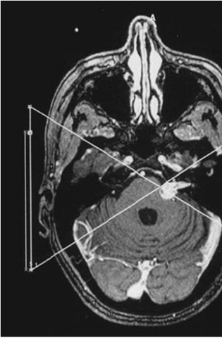
With experience and assistance, a stereotactic frame application should take minimal time. Before applying the frame, the neurosurgeon must have a clear idea of the anatomical localization of the lesion and should bear in mind a suitable entrance point for the probe. When applying a Leksell frame for radiosurgery, the frame must be shifted as much as possible to center the lesion in Leksell space (Fig. 1A). Failure to do so may result in a collision with the collimation helmet. When using CT data, the surgeon must remember that the headpins may cause significant artifact, which may obscure the target if small, as might the beam-hardening artifacts of the temporal bone if the lesion is located in a low temporal or posterior fossa location. Frame application may be performed at the bedside or in the operating room and is most easily accomplished with the patient in the sitting position. Our preference is to sterilize the scalp with an alcohol or betadine prep without shaving hair. The assistant stands either behind or on the side of the patient and stabilizes the ring. The ring should be applied parallel to the cranial floor through the use of ear bars, but some frame parallax is acceptable. As one exception, Leksell frame application must be within 3 of the coaxial imaging plane of Leksell Gamma Plan rejects further attempts at treatment planning for radiosurgery. We anesthetize the scalp and periosteum with a mixture of 9 parts 0.5% Marcaine (bupivicaine) and 1 part sodium bicarbonate, which reduces the burning sensation of the local anesthetic. With adequate local anesthesia, we have obviated the need for sedation. We prefer to place the two posterior pins first and then we place the anterior pins and hand tighten all four pins, before using the wrench, with a two-fingers method. During the frame application, the patient may be injected with intravenous contrast if the localization scan is to be performed immediately after the procedure. Otherwise, the patient can return to the bed with a pillow under the neck for comfort.
Target Localization for Stereotactic Biopsy
Imaging modality should depend on the modality that best demonstrates the lesion: either CT, MRI, or angiography. Basic principles that should be applied when planning a trajectory to target. The instrument’s trajectory should avoid eloquent brain and breach only one pial surface to minimize the change of hemorrhage. This is particularly true for lesions near the sylvian fissure or pineal region. When possible, the instrument should penetrate the brain parallel to white matter tracts, especially when interested in brainstem lesions. Generally, the majority of the cerebrum, basal ganglia, thalamus, and brainstem can be approached with entry points anterior to the coronal suture. For lesions in the occipital, parietal, temporal lobe or the pineal region, a superior parieto-occipital approach is better. Temporal lesions may, additionally, be approached laterally and cerebellar lesions approached posteriorly.
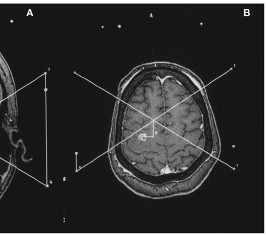
With the patient still in the scanner, it is important to ensure that all fiducial markers are visible on all images. With the advent of MRI-compat-ible localizers, MRI has provided superior target identification. Typically an axial T-1-weighted gadolinium-enhanced image will provide enough spatial information for target localization. For deep grey matter lesions, coronal and sagittal images provide ring and slide angles for isocentric frames (Fig. 2A and B). For brainstem lesions near midline, we recommend frontal lobe entry points with long-axis trajectories to avoid additional pial planes. For such cases, we obtain fiducial and target coordinates in all three orthogonal planes and average the three paired coordinates with the greatest spatial accuracy, eliminating the coordinate in each orthogonal plane which is, by definition, less accurate because of volume averaging. We always select a contrast-enhancing target if present, or abnormal signal visualized in a FLAIR sequence, if not.
The Leksell Frame
After an inspiring visit with Spiegel and Wycis in Philadelphia, Leksell developed his first stereotactic frame [5]. His design included an arc system that was attached to a patient’s head with pins such that the center of the arc corresponded to the selected target. The radius of the arc in the Leksell system is 190 mm, and stereotactic space is designated in a Cartesian coordinate system with center established, in millimeters, at x = 100, y = 100, and z = 100 and zero, by convention, is right, posterior, and superior. This elegant system allows the surgeon the opportunity to quickly and easily establish the target’s coordinates on the MRI or CT monitor. The frame center at x and y = 100 is determined at the center of the intersecting lines drawn from the fiducial points at the corners of the localizing frame, as long as the frame is maintained in an orthogonal relationship with the scanner table. This may be confirmed with a carpenter’s level; periodic adjustments of the frame attachment to the table may be needed. The Leksell z coordinate is established by measuring the distance from the ipsilateral superior fiducial coordinate to the diagonal coordinate and adding 40 mm (Fig. 1A and B). Alternatively, the images can be transferred by tape or ethernet to a surgical planning system. For Gamma Knife radiosurgery, we cross-check the treatment planning software determination (Leksell Gamma Plan) with the manually derived coordinates. If a lesion is left, posterior, and superior, for example, its location should be associated with x > 100, y < 100, and z < 100. For stereotactic surgery, the arc can be moved in the x, y, and z directions to allow for any entry point above the head ring, and the titanium frame is both CT and MRI compatible. Additionally, there is a localizer that can determine coordinates for angiographically obtained targets. Finally, there is no phantom frame with this system.
BRW/CRW Frames
In 1977, Theodore Roberts and a third-year medical student, Russel Brown, were responsible for developing the Brown-Roberts-Wells System (BRW) at the University of Utah [6]. This originally CT-based system consists of a skull base ring with carbon epoxy head posts that offers minimal CT interference. The ring is attached to the patient with screws that are tightened into the skull. The localizer unit is secured to the ring with three ball-and-socket interlocks and consists of six vertical posts and three diagonal posts, creating an "N” shaped appearance [7]. It is this latter ”N” construct that establishes the axial CT plane relative to the skull base by calculating the relative distance of the oblique to the vertical rods. Target coordinates are established by first identifying the axial slice that best features the lesion. The x and y coordinates for each of the nine fiducial rods are identified on the CT or MRI monitor, as are the x and y coordinates for the target. All coordinates are entered into a laptop computer (the SCSI), which computes the target coordinates in BRW stereotactic space. The BRW system then further includes a movable arc and a probe holder. The arc guidance frame has four motions that create infinite different probe pathways, but for any trajectory, the computation must include entry coordinates [8]. Additionally, this system included a phantom base onto which the stereotactic frame including the arc could be placed to test the accuracy of the settings.
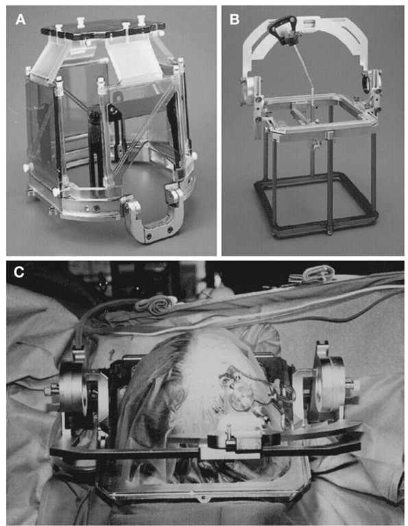
In the 1980s, Wells and Cosman simplified and improved the BRW by designing an arc guidance frame similar to the Leksell frame. The arc system directs a stereotactic probe isocentrically around the designated target, thus obviating a fixed entry point. The Cosman-Roberts-Wells (CRW) system included some of the same design elements as the BRW system, including a phantom frame, the same CT localizer, and the same probe depth fixed at 16 cm (Fig. 3A-C). New innovations included the introduction of MRI-compatible frames and localizers (Fig. 3A), and versatility in arc-to-frame applications that enabled inferior trajectories into the posterior fossa or lateral routes into the temporal lobe. For institutions with the Radionics OTS frameless image guidance system, target and trajectory calculations can now be performed with the OTS intraoperative workstation, which provides more flexibility than the SCS1 laptop.
COMPASS
The COMPASS system is specifically designed for volumetric tumor surgery and evolved from the Todd-Wells frame [9]. A removable head frame can be accurately replaced. This is particularly helpful if data acquisition and surgery are performed on separate days. There is, similarly, an arc frame with a 160-mm radius and 2° of freedom to allow a multitude of trajectories. There are localizer frames that are compatible with CT, MRI, and angiogram. Finally, the most unique aspect of the COMPASS system is that the head frame fits into a motor-controlled slide, which can move the head within a fixed arc-quadrant and allow computer control and volumetric surgery.
WHICH FRAME IS "BEST?"
The quotes around the last word sum up the answer succinctly—there is no one ”best” system or concept. Neurosurgeons or institutions seeking to purchase their first stereotactic frame may find various reasons for making a choice.
Figure 3 Cosman-Roberts-Wells (CRW) stereotactic system. A, MRI-compatible headring with attached Universal Compact Localizing Frame (UCLF). B, Rectilinear phantom pointer (RLPP) with CRW stereotactic frame calibrated to phantom target. The RLPP is also used for isocenter verification in the X-knife stereotactic radiosurgery system. C, Intraoperative view of CRW-based stereotactic biopsy for lesion in the right frontal lobe.
These might include a factor as simple as familiarity with one device from one’s training. Service from a vendor may be better in a particular region for a certain system. Also, as noted, this topic does not provide a comprehensive list of all commercially available stereotactic frames. With the Leksell and Radionics CRW frames being the most commonly used devices, neurosurgeons may keep in mind the following:
1. The Leksell frame has a simpler system for instrument insertion to the desired target. No special measurements are necessary, as the zero point on the arc carrier is 19 cm from the target. It is lighter than the CRW frame. X, y, and z coordinates can be derived quickly from a two-dimensional image without a computer.
2. The CRW frame is accurate without the need for orthogonal positioning of the frame; patients may be scanned without rigid attachment of the frame to the table (although this may be desirable for other reasons, such as, eliminating head motion during a ra-diosurgical scan). It has a phantom base that can be sterilized and used in the operating room to confirm that accurate targeting has been planned. Although not the standard method, stereotactic coordinates can be derived directly from an image IF the scan was done with the frame in an orthogonal position.
3. These systems may be used as part of surgical navigation systems, wherein the stereotactic scans and frame coordinates are automatically read by the dedicated computer workstations, and target coordinates derived by clicking on the desired point on a particular image.
Conclusion
Modern CT and MR-guided stereotactic frames provide spatial accuracy for both stereotactic instrumentation and stereotactic radiosurgery. Despite the development and widespread use of frameless image-guidance systems, frame-based systems will remain an important tool in neurosurgical practice. For speed, ease, accuracy, and reliability, frames are the best method for performing point stereotaxis for biopsy and functional stereotactic neurosurgery.


![tmp1A-3[4] tmp1A-3[4]](http://what-when-how.com/wp-content/uploads/2012/05/tmp1A34_thumb1.jpg)
![tmp1A-4[4] tmp1A-4[4]](http://what-when-how.com/wp-content/uploads/2012/05/tmp1A44_thumb1.jpg)

