Introduction
Electric propulsion, the propelling of space vehicles by streams of electrically charged and electrically accelerated particles, is one of the most exciting concepts of the space adventure. It represents a fascinating area of applied science and technology, and it also provides the only feasible means of exploring the farthest reaches of our solar system by economically transporting large manned expeditions and heavy payloads to neighboring planets and probing the solar system away from the ecliptic plane.
The concept of the ion rocket engine (the most useful form of electric propulsion for space missions) has existed for some time. R.H. Goddard alluded to the possibility by an entry in his notebook dated 1906, and in 1929, H. Oberth discussed it in his classic topic Wege zur Raumschiffahrt (1). However, the concept had to remain of only academic interest until the advent of the space age, and, particularly, until generating large amounts of electric power in space became a physical possibility. When solar-electric power source technology was established, the latter requirements, of course, became fulfilled.
In the United States, active interest dates back to about 1954 when NASA’s Dr. Ernst Stuhlinger published some comprehensive space system studies on the subject of electric propulsion (2). The first experiments on ion engines started about 1958, and an accelerated effort continued through the 1960s and 1970s. The ion engine matured during the 1980s and 1990s, and functional satellite and deep-space missions occurred in the late 1990s.
In general, an electric propulsion system has a power plant that consists of an energy source and a means of converting this energy into electrical energy and a propulsion device that converts the electrical energy into directed kinetic energy of its propellant. The two major problem areas of electric propulsion are 1) the development of sources of electrical energy that are sufficiently lightweight and 2) the transfer of this energy to the propellant to provide high exhaust velocities efficiently. The first problem, along with the general need for power in space, has given strong impetus to fundamental and applied work in developing lightweight solar panels. These areas of research and development have been vital to the future of electric propulsion and obviously have impacted many other important satellite and spacecraft applications. A solution to the second problem, an efficient propulsion device, is the subject of this article (3).
Relationship to Chemical Rockets
Before proceeding with the discussion of ion propulsion, it might be well to relate it to the more conventional types of rocket propulsion, both in terms of its basic mechanism and of the types of missions for which it is required. Thrust is equal to the rate of change of momentum imparted by the exhaust of a rocket engine. For simplicity, let it be assumed that all particles in the exhaust have the same velocity vex. Then the thrust T is simply

where Mp is the propellant mass flow rate. Thus, if we can increase the exhaust velocity, a smaller expenditure of propellant is required for a given thrust. From a slightly different point of view, consider the equation of motion in free space for a vehicle whose mass M and velocity v are functions of time:
![]()
Hence, for an initial mass Mi, starting from rest,

This relation tells us that the effectiveness of mass expenditure (Mi — M) to gain velocity is a function of exhaust velocity, that is, from a mass point of view, a given velocity increment is achieved more efficiently from a system that has high exhaust velocity.
Now, in a chemical rocket engine, burning a fuel generates thrust; the hot gases from the combustion process are expelled through a nozzle at an exhaust velocity related to the temperature of the burning propellant. This temperature, in turn, is limited by the chemical energy content of the fuel. Thus, in a chemical system, exhaust velocity is low and consequently, from equation 1, the mass flow rate is very high. These systems, of course, have high thrust and are needed to overcome gravitational forces and to inject payloads into orbit. However, for many projected space missions starting from an Earth orbit or after Earth escape, the tremendous mass of a chemical rocket that would be necessary to deliver a heavy payload to, say Jupiter, may be completely unfeasible.
It is evident that the acceleration of ions (e.g., in ion thrusters) to any desired velocity is completely unrelated to thermal heating: the exhaust velocity can be adjusted to any desired high value, resulting in great fuel economy. We replace the high-thrust chemical systems and their huge weight ofpropellants by low-thrust electrostatic systems that operate for extremely long periods of time and require much lighter fuel loads.
Specific impulse is a measure of exhaust velocity. If a thrust T lasts for a time t, the total impulse imparted to the space vehicle is Tt. Then, the specific impulse, defined as impulse per unit weight of propellant exhausted, is

where Wp = Mpg is the propellant weight. Combining equations 1 and 4, we obtain
![]()
which identifies specific impulse as a measure of exhaust velocity.
The best chemical systems have specific impulse values slightly more than 300 s, whereas ion rocket engines efficiently provide values of specific impulse from around 3000 s on up—a factor of 10 or more better than the most advanced chemical systems.
For any particular space mission, an optimum value of specific impulse (or exhaust velocity) will always exist that results in a minimum overall system weight (viz., useful payload, engine, and propellant), which must be boosted into the initial Earth orbit or beyond. This concept is illustrated in Fig. 1 and arises as follows. At low Isp, the propellant mass is high, whereas at high Isp, the weight of the electric power supply increases (power-supply weight is roughly proportional to power and, in turn, the power in the exhaust beam is proportional to the product of thrust and exhaust velocity). Thus, the optimum specific impulse involves a compromise between power-system weight and propellant weight and is larger, the more energetic the mission. From Fig. 1, we also see that the optimum specific impulse depends on the slope of the power plant weight curve, that is, the power plant weight per unit power output ap. This parameter is commonly designated power plant ”specific weight” and, in general, the lower the ”specific weight” of the power plant for a given mission, the higher the optimum specific impulse. For ion propulsion systems powered by solar panels, the optimum specific impulse falls into the range of 3000-4000 s.
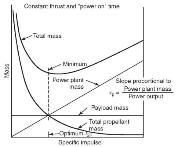
Figure 1. Mass of a complete ion propulsion system.
The low thrust achievable from ion propulsion results from the fact that such systems are power-limited. A power-to-thrust ratio of about 100kW/lb thrust is representative of the current art. This figure will gradually decrease to around 75kW/lb as the technology advances. Thus, for example, power at the several-hundred-watt levels limits the thrust to millipounds. However, when gravitational forces are small (such as for interplanetary spacecraft that have been launched beyond the gravitational pull of Earth) or when they are balanced by centrifugal forces (as in satellites), total impulse replaces thrust as a fundamental requirement. For example, a thrust of one pound that acts continuously for one year produces the same total impulse as a thrust of 500,000 lb that acts for one minute. Therefore, low thrusts, applied for a long period of time and coupled with great fuel economy (high Isp) can make possible a number of long-duration space missions that otherwise would not be feasible.
Table 1. Comparison Chart
| Spacecraft description | All-chemical | SEP spacecraft,” |
| voyager (4), 190 | 250 days transit | |
| days transit | ||
| Injected weight (not including launch vehicle) | 7800 lb | 9600 lb |
| Power level | All chemical | 23 kW |
| Approach velocity | 4.3km/s | 1.8km/s |
| Weight at approach | 5295 lb | 5140 lb |
| Weight in orbit (excluding retro inert weight) | 1850lb | 3598 lb |
| Orbit spacecraft fraction | 0.35 | 0.70 |
| Lander weight | 2300lb | 2300 lb |
| Scientific payload | 470 lb | 1793 lb |
| Percent scientific payload weight at approach | 8.9% | 34.9% |
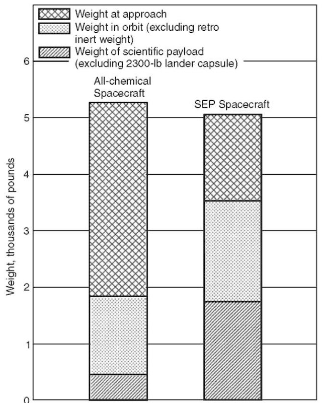
Figure 2. Performance comparison.
A Mars orbiter mission was selected as a basis of comparison between an all-chemical propulsion spacecraft mission and one in which chemical propulsion is augmented by an appropriate solar-powered electric propulsion system. A 2300-lb lander capsule is carried by both spacecraft and it is assumed, separates from the bus before retro into orbit. The weight breakdowns are presented in Table 1. The results (see Fig. 2) indicate that although the weight at approach is comparable for both spacecraft, the electric propulsion spacecraft places useful weight in orbit almost twice that of the all-chemical spacecraft. More significant is the fact that the actual scientific payload placed in Mars orbit by the electric propulsion system is nearly four times that of the all-chemical spacecraft.
Generic Types of Electric Propulsion Thrusters
We have compared ion propulsion to chemical propulsion from a performance standpoint. Now, let us briefly look at the technological differences among the various forms of electric propulsion devices.
General Principles. Over the years, there have been varying approaches to the electrical generation of thrust, characterized by their acceleration mechanism. These thrusters are classified as 1) electrothermal or thermally heated (5), 2) electromagnetic or plasma (6), and 3) electrostatic or ion (7).
Electrothermal. Electrothermal thrusters generate thrust by increasing the enthalpy of the propellant (such as hydrogen) by raising it to very high temperatures. The gas is then expanded through a nozzle where its thermal energy is converted into directed kinetic energy.
Electromagnetic. Electromagnetic thrusters generate thrust by ionizing the propellant and driving high currents through the resultant plasma. The current-carrying plasma conductors interact with the self-field of the net current in the plasma and discharge electrodes to accelerate the entire plasma. Consequently, electromagnetic thrusters are called plasma thrusters.
Electrostatic. This article deals with electrostatic or ion thrusters that generate thrust by ionizing the propellant gas and then by accelerating ions in an electrostatic field. It is more advanced than plasma propulsion in the sense that much progress has been made in solving the basic problems (such as efficiency and life) and that ion engines are presently being manufactured and are available for actual high-energy missions.
Specific Examples Of Generic Types. The three basic electric-propulsion types generally described before are further sub divided into a number of specific devices. A partial listing of these devices is presented in Table 2. Figure 3 shows an example and some design specifics for each generic type of electric propulsion thruster. Now, a brief description of each.
Resistojet. In a resistojet, the propellant is heated by energy transferred from an electrically heated element (resistor). One class of resistojet, the augmented hydrazine thruster, uses electric power and/or catalyst beds to initiate and sustain decomposition of the hybrid hydrazine. The vaporized hydrazine is then passed through a heat exchanger where additional energy is added to the propellant. Res is to jets achieve a specific impulse of about 300 s and a thrust-to-power ratio of about 575 mN/kW; this makes them well suited for low Dv applications, such as drag makeup and modest orbit raising. Approximately 200 resistojets have been flown on US satellites since 1983.
Table 2. Electric-Propulsion Thrusters
| Electrothermal technologies Resistojet Arcjet Electromagnetic technologies Magnetoplasmadynamic (MPD) thruster Pulsed plasma thruster Pulsed inductive thruster (PIT) Rail accelerators Electrostatic technologies Electron-bombardment ion thrusters Hall-effect ion thrusters Surface-contact ion thrusters |
Arcjet. In the arcjet, the propellant stream is heated by an electric discharge arc struck between the thrust chamber wall (i.e., the anode) and a tungsten cathode. As in the resistojet, the hydrazine arcjet uses a catalyst bed to decompose the propellant before it enters the arc chamber. Low-power arcjets achieve an Isp of about 500 s and produce a thrust of e 230 mN using input power of 1.8 kW. Although a high-power («30kW) arcjet has been demonstrated in a short-duration space test, the most prominent use of the arcjet has been for North-South stationkeeping on communications satellites. Approximately 100 arcjets have been launched on commercial satellites since 1993.
Magnetoplasmadynamic (MPD) Propulsion. The electrode and discharge configuration of a self-field MPD thruster is shown in Fig. 3. Gaseous propellant is introduced between the cathode and anode, and a voltage pulse is applied to ionize the gas and produce current flow between cathode and anode, as shown. The current that interacts with the self-fields, as shown, produces force on the conducting plasma. The nozzle-like shape of the anode also contributes some thrust as a consequence of the ohmic heating of the propellant gas by the high discharge current (104 to 105A) and subsequent expansion of the hot gas as it flows through the nozzle.
Hall-Effect Ion Thruster. The Hall-effect thruster, also called the closed drift or stationary plasma thruster, has been under intensive development by the Soviet Union during the past four decades. The Hall thruster accelerates electrons emitted by an external hollow cathode into an annular ionization chamber, which has an anode located at its upstream end. The axial motion of the electrons across an applied radial magnetic field gives them a drift velocity in the az-imuthal direction. The electrons drift in closed paths and produce ions by colliding with xenon gas atoms, hence the name closed-drift thruster. The electric field that accelerates the electrons in the upstream direction also accelerates the positive ions in the downstream direction to produce thrust. Typical Hall-effect thrusters achieve an Isp of e 1600 s and a thrust of e 83 mN, when operating at an input power of 1.35 kW. The Soviet Union has launched approximately 100 Hall-effect thrusters on GEO satellites.

Figure 3. Electric propulsion thruster types.
Electron-Bombardment Ion Thruster. In this device, gaseous propellant is supplied to the discharge chamber and ionized by electron bombardment in a Penning-type discharge.1 The accelerator grids extract and focus the ions in a large number of “beamlets” to form a thrust beam. The propellant is exhausted as ions, so an electron-emitting neutralizer is provided to couple electrons into the thrust beam and thereby to balance the charge expelled as ion current.
Emergence of Ion Propulsion (Electron Bombardment Thrusters)
The acceleration concepts identified in the preceding section have both advantages and disadvantages. The development status of the various technologies also differs. In addition, the technological difficulties encountered in development vary among the concepts and thus the emphasis of U.S. research and development has been governed to a large extent by considering the potential benefit versus the technological difficulties. At this time, the electron-bombardment ion thruster is the most mature and the most ground- and space-tested of the high-Isp devices. Hence, it will be our major focus.
Total System Concept. The basic components of a complete propulsion system include an external source of energy (for example, sunlight incident on a solar panel), an energy-management subsystem (that supplies power to the thruster in a useful form), a propellant-supply subsystem, and a thruster that uses electrical power to accelerate the propellant and generate thrust. Space Tests. Because of their inherently low thrust and consequent long operating requirements, extensive testing in laboratories on Earth was essential to the development of ion engines for eventual use in space. Simulating the space environment for an ion engine is much more complex than the usual space-simulation problem. Besides maintaining an excellent vacuum (of the order of 10 ~ 6mmHg) in the presence of a large and continuous high-energy gas loading, in addition to the usual physical environmental factors such as solar radiation and gamma rays, an adequate way must be found to simulate the electrical environment of space. The walls and collectors must not act as sources of electrons. In space, the ion beam is injected into an infinite region that has no boundary conditions, whereas, in a vacuum chamber, the walls and collector impose artificial electrical boundary conditions at the edges and end of the ion beam that may influence the realistic interpretation of an engine’s performance. Another problem concerns sputtering; even a small ion engine that operates for hundreds or thousands of hours can sputter away many tens of pounds of collector material, a difficult problem with which to contend. As difficult as these problems are, they were solved in a number of government and industrial laboratory test facilities. And, as a result, more than 350,000 hours of thruster and component-life tests have been carried out with mercury, cesium, and xenon propellants (9).
Of course, the most definitive testing of ion engines is done in space. A series of ballistic and orbital tests of ion engines have been pursued, three of the most important flight-qualified systems are described here.
Space Electric Rocket Test (SERT I). The SERTI (Fig. 4) was launched from Wallops Island on 20 July 1964 on a four-stage Scout rocket (10). It followed a ballistic trajectory for 47 minutes and had the distinction of being the first successful flight of an ion engine. A NASA Glenn Research Center mercury electron-bombardment thruster operated 31 minutes at a thrust level of 4.5 mlbf and provided data on ion beam neutralization, thrust level, radio communication interference, and differences in performance between ground and space testing. Thrust was measured by determining changes in spacecraft spin rate. From these measurements, it was determined that complete beam neutralization was achieved in agreement with vacuum chamber tests. In addition, there was no communication interference.
Space Electric Rocket Test (SERT II). The SERT II spacecraft was launched in February 1970 (Fig. 5); it contained two 15-cm-diameter mercury electron-bombardment ion thrusters each capable of producing 30-mN thrust and a 4200-s specific impulse at an efficiency of 70% (11). The original flight objective was to demonstrate long-term space operation of ion thrusters by accomplishing operating times of three and five months, respectively, for the two thrusters. Before completing their goals, both thrusters failed due to accelerator-electrode erosion that ultimately resulted in short circuits between the high-voltage electrodes of the beam-extraction system. However, the electrical short in one thruster was eventually cleared, and steady-state thruster operation was reinitiated in January 1979.
In total, the SERT II project demonstrated long-term (i.e., 22.5 years) thruster operation in-orbit and identified a failure mode that occurs only in a zero-gravity environment. Consequently, ion thrusters, now designed, operate with the neutralizer located farther from the accelerator grid, and accelerator voltages are operated at lower values to eliminate the type of erosion that caused the failure of the SERT II thrusters.
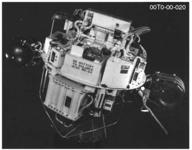
Figure 4. SERT-I ion engine flight test spacecraft
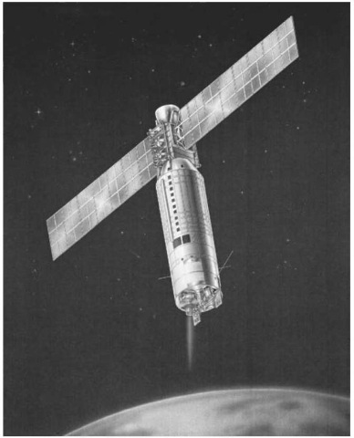
Figure 5. Space electric rocket test spacecraft in orbit.
Ion Auxiliary Propulsion System (IAPS). The objective of the IAPS technology program and test flight was to develop a prototype 4.5-mN electron-bombardment thrust system and subject it to flight-qualification-level testing and long-term space operation. The test plan included operating one thruster cyclically to demonstrate the durability of the subsystem during a simulated 7-year North-South stationkeeping mission on a typical geosynchronous satellite. This test schedule implied completing 2560 cycles of 2.8 hours each, a total of 7200 hours of thrusting time. In the actual flight test, a 2-hour thruster-off period was planned between operational periods, resulting in 17 months of spacecraft operating time.
The IAPS flights hardware (12,13) consisted of two 8-cm thrust systems and a diagnostic instruments package (the two IAPS units are shown in Fig. 6). The IAPS ion thruster developed 4.5-mN thrust and operated at a specific impulse of about 2500 s at an overall efficiency of 40%. The power electronic unit contained nine independently programmable power supplies. A digital-control-interface unit provided the power-and-command interface between the user and the thrust subsystem. The digital-control interface was a signal-processing unit that transmits power and 16-bit serial digital commands. It contained a microprocessor that had all of the control algorithms to provide several set points for heater and vaporizer supplies, as well as proper sequencing of thruster operations.
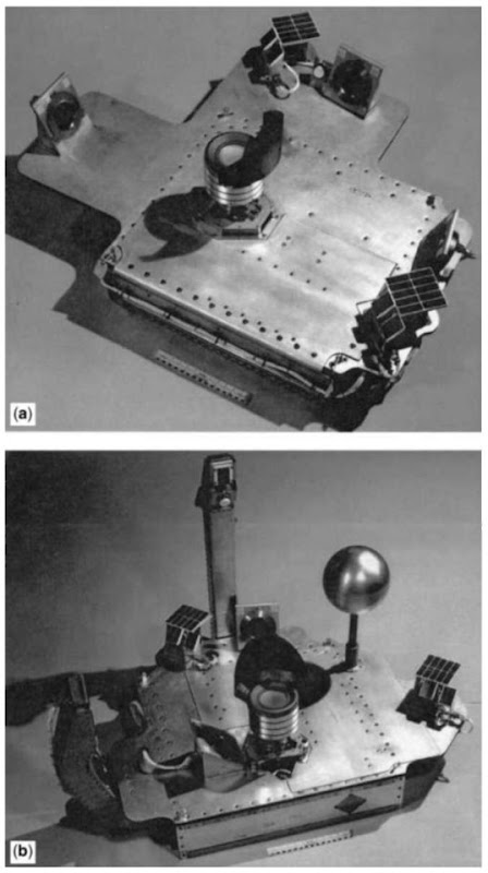
Figure 6. External components of IAPS modules include the ion thruster (shown at center) surrounded by diagnostic instruments. (a) Ram/wake module; (b) Zenith module.
The IAPS flight hardware was successfully subjected to extensive ground testing and was delivered to the spacecraft contractor for integration in July 1982. Spacecraft integration testing began in February 1983. However, the scheduled launch was canceled because of budgetary constraints. Transition to Xenon. From a purely propulsive standpoint, the optimum propellant is one that has the largest atomic mass. Consequently, early development emphasized mercury propellant and mercury ion thruster technology. However, the use of gaseous propellants that are non toxic and nonconden-sable has several advantages over mercury from overall system and program considerations. For cyclic thrust requirements, ion thrusters operating on gaseous propellants do not require complex thermal designs or carefully orchestrated preheating to prevent propellant condensation during thruster start-up. In addition, thrusters operated on gaseous propellants can be shutoff abruptly without an uncontrolled loss of neutral propellant during thruster cooldown after the thrusting period. In ground testing, thruster propellant flow can be measured without waiting for the thruster to reach thermal equilibrium. Because of these system and program considerations, advanced thruster development became focused on thruster operation using inert gases.
Inert-gas ion thrusters require higher ion beam current to produce a given thrust; this increase in current is inversely proportional to the ion mass (at constant specific impulse). Consequently, inert gas thrusters must produce ions more efficiently in the discharge chamber (measured in watts per beam ampere). Using advanced discharge chamber designs, thruster efficiencies have been obtained from Xe, Kr, and Ar (14) propellants that equal or exceed mercury ion thruster performance (e.g., total efficiency2 = 70%) for a specific impulse in the range of 3000-6000 s.
Inert-gas ion thrusters require fewer power supplies and may be controlled by using less complex algorithms than those required for controlling mercury ion thrusters (because thruster thermal variations do not change propellant flow characteristics). Hence, since 1984, development programs have been directed toward xenon electron-bombardment ion thrusters.
Detailed Thruster Design and System Description. The xenon electron-bombardment ion thruster is now the primary contender for both auxiliary and primary propulsion applications in the near future, so we will emphasize and detail the descriptions of this thruster and its associated propellant feed and power conditioning subsystems. These descriptions will include some of the physics as well as engineering aspects of the resulting ion propulsion systems.
A schematic of the xenon ion thruster (15) is shown in Fig. 7. The thruster consists of an ionization chamber, an ion-extraction assembly, and an ion-beam neutralizer, typically, the ionization chamber is a cylinder with an electron-emitting hollow cathode (16) located at one end and an ion-extraction assembly located at the other. Xenon atoms enter the ionization chamber through the propellant plenum (about 80% of the total gas flow) and the hollow cathode (about 10% of the total flow). Electrons emitted by the hollow cathode are attracted to the cylindrical wall, or anode, which is maintained about 30 volts positive with respect to the cathode by the discharge power supply. The electrons are prevented easy access to the anode by a magnetic field, which is generated by rings of rare-earth permanent magnets (14). The energetic electrons work their way across the magnetic field lines by collisions, primarily with xenon atoms.
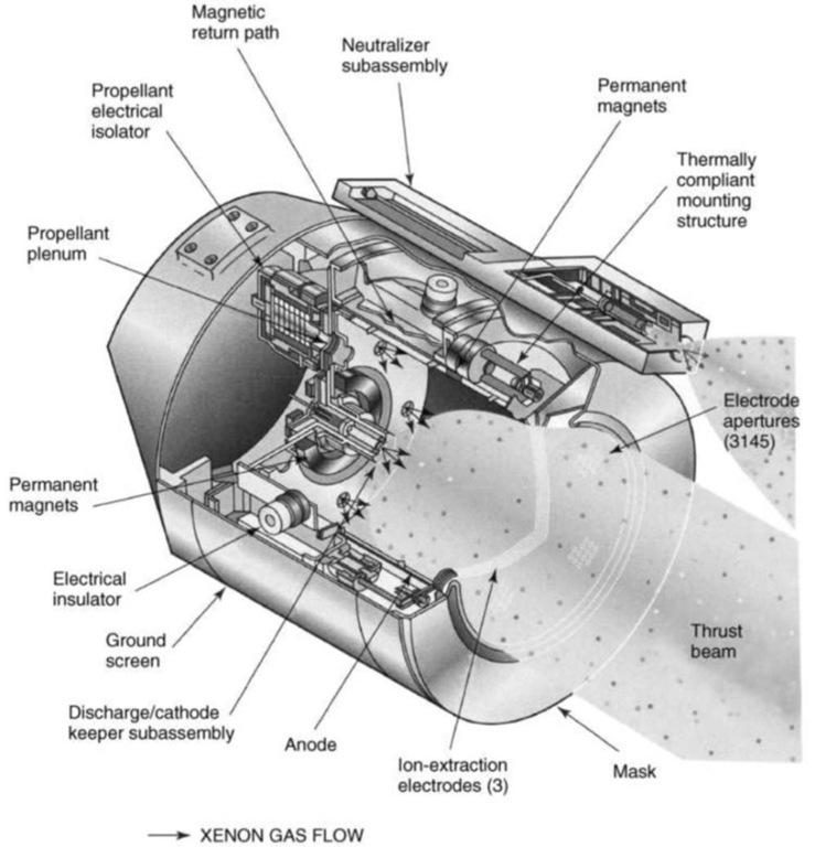
Figure 7. Schematic of xenon ion thruster.
Some of these electron-atom collisions result in ionizing the atom, and electron is released to form a positive xenon ion Xe +.
Under normal operating conditions, the ionization chamber is filled with plasma, in which the ion and electron densities are about 1017m ~3 and the xenon atom density is about 1018m ~3. Ions preferentially drift toward the downstream end of the chamber at a velocity (the Bohm velocity) determined by the electron temperature, which is e5eV. The gas atoms have a speed determined by the wall temperature, which is e500K. As a result of the tremendous difference in their velocities, ions exit the chamber at a rate about 10 times greater than the atom loss rate; discharge propellant utilization efficiencies of 90% or more are typical of these devices.
The ion-extraction assembly consists of a pair of grids, or electrodes, that are spaced very closely (e 0.5 mm) and contain several thousand precisely matched apertures. The inner, or screen, grid is maintained at a positive potential of the order of 1kV (with respect to the spacecraft) by the screen power supply. The outer, or accelerator, grid is maintained at a negative potential of the order of a few hundred volts by the accelerator power supply. As the ions approach the apertures in the screen grid, they are attracted by the negative accelerator grid and are accelerated through the sum of the potentials applied to the two grids plus the anode voltage. After the ions exit to space through the accelerator apertures, they are decelerated to essentially zero potential (space-plasma potential). As a result of this acceleration/deceleration action, the sum of the voltages applied to the anode and screen grid determines the final velocity of the ions. The negative potential of the accelerator grid also provides an electrostatic barrier that prevents the positive potential of the screen grid from accelerating electrons in the ion-beam plasma through the apertures in a direction opposite to the ion flow.
Some ion thrusters use a third electrode, or decelerator grid, located downstream of the accelerator grid. The decelerator grid establishes the precise axial location of the neutralization plane, and it allows more freedom in selecting the voltages applied to the screen and accelerator grids (i.e., selection of the accelerator/decelerator ratio). A decelerator grid also has the advantage of shielding much of the spacecraft from direct view of the accelerator grid. This shielding is important because the accelerator grid undergoes charge-exchange ion sputtering during thruster operation and is a potential source of contamination for sensitive elements of the spacecraft, such as solar arrays, thermal radiators and blankets, and optical sensors.
The ion-beam neutralizer (17) consists of a hollow cathode similar to the one that supplies electrons to the ionization chamber. The neutralizer provides electrons to match the ion-beam current and to neutralize the space charge of the positive ion beam. Current neutralization is required to prevent the spacecraft from charging negatively due to the ejection of positive charge. Space-charge neutralization is required to prevent excessive divergence of the positive ion beam due to the mutual repulsion of like charges. The neutralizer cathode consumes propellant but produces essentially no thrust. Therefore, highly gas-efficient neutralizers are necessary to achieve high specific impulse and thruster efficiency. The neutralizers in use today consume as little as 6% of the total xenon required for thruster operation.
The lines that provide xenon to the propellant plenum, discharge cathode, and neutralizer cathode contain propellant electrical isolators, such as that shown in Fig. 8. These devices allow keeping the propellant storage and control system at the spacecraft (ground) potential, whereas the thruster components may be at potentials as high as kilovolts. The isolator consists of a cylinder constructed of alumina that has overlapping shields surrounding its outer surface to prevent it from being coated by sputtered electrically conductive material, especially during ground testing. A stack of stainless steel screens and alumina spacers is contained within the body. The thickness of the spacers ensures that the voltage across adjacent screens is less than the minimum Paschen breakdown voltage for xenon. By this arrangement, the applied voltage divides linearly along the length of the isolator, and the number of individual screen/ isolator elements establishes the total voltage-isolation capacity.
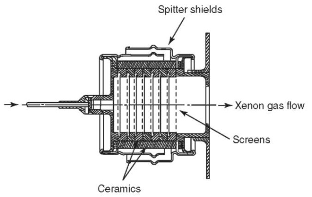
Figure 8. Propellant electrical isolator.
A power processor unit (PPU) provides the currents and voltages required to power the various components of the thruster and the controls for programming the individual power supplies for startup, steady-state operation, shutdown, and over current protection. Typical power supply outputs for auxiliary and primary propulsion thrusters are listed in Table 3. The PPU receives its input power directly from the spacecraft bus and typically provides seven outputs to the thruster in the form of regulated currents or voltages.
The xenon storage and control system consists of a high-pressure tank and a flow controller. Xenon is stored at an initial pressure of about 100 atm, where its specific gravity is about 1.65. The gaseous xenon is metered into the thruster cathodes and the ionization chamber by a flow controller that may be an active or a passive system. Active flow controllers use valves and plenum chambers to maintain the individual gas flows at constant values or to control them in proportion to critical thruster electrical parameters such as the anode voltage, neu-tralizer keeper voltage, and beam current. Passive flow controllers use a pressure regulator and individual orifices to provide constant gas flow rates to the two cathodes and the ionization chamber. The required (constant) gas flow rates are determined during initial flight acceptance testing of a thruster.
Ground and Space Life Tests. The first long-term life test of a xenon ion thruster was completed in 1988 (18). This test was actually a wear-mechanism test involving a 25-cm-diameter laboratory-model thruster that had not been designed for space application nor fabricated or assembled using the quality standards imposed on high-reliability space hardware. In spite of the level of the hardware involved, this test was successfully completed after achieving 4350 hours of accumulated ON time in 3850 ON/OFF cycles of approximately 1-h duration.
Table 3. Power Supply Output Characteristics for Auxiliary and Primary Propulsion Applications of Xenon Thrusters
| Output/Application | Auxiliary propulsion | Primary propulsion |
| Screen | 0.5 A at 750 V | 3.5A at 1200V |
| Accelerator | 10 mA at 200 V | 100 mA at 450 V |
| Discharge | 4A at 40V | 21 A at 40 V |
| Discharge keeper | 1 A at 15V | 1A at 10V |
| Discharge heater | 3.6 A at 10 V | 3.8A at 12V |
| Neutralizer keeper | 1 A at 15V | 1A at 10V |
| Neutralizer heater | 3.6 A at 10 V | 3.8A at 12V |
The thruster was operated at an input power of 1.3 kW and produced about 65 mN of thrust at a specific impulse of 2800 s. The hours and cycles successfully demonstrated before the test was terminated were approximately twice the operating requirements of this thruster for the intended application of N-S sta-tionkeeping on a large spin-stabilized communications satellite.
Several additional life tests of engineering-model and flight-model xenon ion thrusters have subsequently been performed at NASA, JPL, Hughes Electronics, and elsewhere, involving thrusters that ranged in size from 10- to 30-cm beam diameter (19-21). The longest duration life tests of xenon thrusters are currently underway at Hughes Electronics and had accumulated 13,000 and 14,000 hours when this article was written. These units have 13-cm-diameter beams and operate with an input power of about 440 W to produce 18 mN of thrust at a specific impulse of 2565 s. The highest power life test is also currently underway at Hughes Electronics, and when this article was written, it had accumulated more than 1500 hours at an input power of 2 kW and an additional 3000 hours at an input power of 4.2 kW. This unit has a 25-cm-diameter beam, and at these power levels, it produces 80 or 165 mN of thrust and achieves a specific impulse of 3700 s.
Life testing of xenon ion thrusters has confirmed that operating times of 10,000 to 20,000 hours are feasible and that the primary life-limiting mechanisms are accelerator-grid erosion due to sputtering by charge-exchange ions and screen-grid erosion due to sputtering by doubly charged ions. The charge-exchange ions are formed in the ion acceleration and deceleration regions, which contain both primary beam ions and un-ionized xenon atoms. In the resonant charge-exchange reaction, an electron is exchanged between the atom and ion, creating a slow charge-exchange ion. Sputtering of the negative accelerator grid occurs when the charge-exchange ions are accelerated to it.
The plasma potential within the ionization chamber is roughly equal to the anode potential. Therefore, surfaces that are at cathode potential, such as the screen grid, are continuously bombarded by ions that fall through the anode-to-cathode voltage. Doubly charged ions are formed within the ionization chamber, primarily by a multistep ionization process in which a singly charged ion is bombarded by an electron. The doubly charged ions are particularly damaging because they strike the screen grid at energies equal to twice that of a singly charged ion. The sputter yield of typical grid materials, such as molybdenum, increases exponentially with ion energy, and models of the screen grid sputtering show that nearly all the sputtering in ion thrusters is caused by doubly charged ions (22,23).
Other components that could limit the lifetime of ion thrusters include the cathodes and associated heaters. However, cathode-life tests (24) have successfully achieved 28,000 hours of cyclic operation on xenon, and heater tests have demonstrated more than 45,000 ON/OFF cycles.
Xenon thrusters have been flight-qualified by rigorous ground testing in a variety of sizes, including beam diameters of 10, 13, 25, and 30 cm, and the 13-, 25-, and 30-cm-diameter thrusters have also been space-qualified on commercial or scientific spacecraft. Hughes Electronics has launched 10 communications satellites that use their 13-cm and 25-cm xenon ion propulsion subsystems (XIPS) for station keeping, orbit raising, momentum dumping, and attitude control. When this article was written, more than 7000 hours of operation had been accumulated on the 40 XIPS thrusters that have been launched, and more than 57,000 hours of acceptance, qualification, and life testing had been accumulated in ground testing.
Manufacturing Status. For xenon ion propulsion systems to be widely applied to satellite and planetary/interplanetary missions, an industrial manufacturing capability must be developed. The beginning of this production capability has already been initiated with significant effect. For example, Hughes Electronics already maintains a production-line manufacturing capability for both 13- and 25-cm thrusters, and their current manufacturing and test capacity is about six flight units per month.
In addition to manufacturing satellite control propulsion systems, producing new primary propulsion systems is already underway. This latter production need was initiated by NASA’s Deep Space 1 (DS-1) mission, which used a 30-cm-diameter thruster and PPU (called the NSTAR system, NASA Solar Electric Propulsion Technology Applications Readiness) for its primary propulsion (25,26). The DS-1 spacecraft, shown in an artist’s conception (Fig. 9), propelled by the NSTAR ion-propulsion system, covered a distance of more than 150 million miles on a trajectory that featured flybys of the asteroid Braille and the comets Wilson-Harrington and Borrelly. The successful completion of the DS-1 mission qualified solar electric propulsion for use on future NASA missions, both Earth-orbital and deep space. As a result, an industrial manufacturing capability for the NSTAR thrust system has been established at Hughes Electronics.
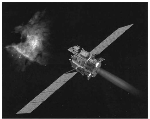
Figure 9. Deep Space 1 (DS-1) spacecraft
Applications
Space-mission interests and opportunities continue to expand as they reflect the capability of space launchers, new mission requirements, space policies, and economies of scale. Future space missions will become increasingly demanding in energy and duration. Therefore, they will profit more significantly from using ion propulsion.
These missions range from near-Earth vehicle precision position control and orbital change to interplanetary missions. During the past decades, the specific payoff of ion propulsion has been identified for each of these broad ranges of applications; a sampling of these results are reviewed in the following paragraphs with more specific descriptions.
Synchronous Satellites (Auxiliary Propulsion). Two sources of perturbing forces dictate the control system requirements for maintaining a satellite stationary in a 24-hour orbit: the gravitational attraction of the Sun and Moon and the triaxiality of Earth (e.g., see Fig. 10). The magnitude and nature of these perturbations determine the design and mode of operation of the ion propulsion station keeping system.
However, because correction for the triaxial perturbation (27) requires thrust in an E-W direction or perpendicular to that of the N-S solar-lunar effect correction, either separate or gimbaled ion thrusters would be required. Because of the low energy required, this E-W correction under normal conditions would not be considered a highly useful application of ion propulsion. Therefore, let us concentrate on N-S satellite station keeping.
General Considerations. Of all celestial bodies, only the Sun and Moon produce significant perturbing effects on an Earth satellite at synchronous altitude. The force of attraction from these two bodies can be divided into three components: two, the radial and tangential, lie in the equatorial plane, and the third lies normal to this plane. The radial and tangential components produce cyclic oscillations in satellite radius and longitude. It can be shown that these oscillations have a small maximum amplitude throughout each satellite orbital period and that at the end of that time, both the change and rate of change of satellite radius and longitude will have assumed their initial zero values. Hence, no corrective thrust is required to counteract the radial or tangential force components.
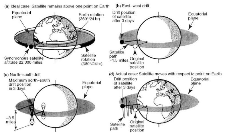
Figure 10. Synchronous satellite perturbations.
The component of force normal to the equatorial plane (for synchronous satellites, this will be referred to as the north-south or “Z” component) will, however, cause an oscillation that results in increasing the satellite’s orbital inclination at an initial rate of 1° per year (28). The amplitude of this oscillation will grow to a maximum of 20° in about 40 years. If the satellite is to remain stationary in the equatorial plane, it is necessary to correct this perturbation. The optimum mode of correction and the magnitude of thrust can be determined by solving the appropriate differential equation while taking corrective thrust into consideration.
The solution to this equation is shown in graphical form in Fig. 11 (29), where the uncorrected Z-oscillation is given for a 48-day interval during which the Sun passed through a point of maximum perturbation. The maximum Moon effect occurs every 13.6 days. Figure 11c illustrates the total solar-lunar effect on a satellite’s orbital inclination for a representative 48-day period. The inclination at the end of this time is 0.16°. The effects of solar and lunar perturbations are shown separately for the same period in Figs. 11a and 11b, respectively. The total change per year in orbital inclination can be determined from these curves. The Sun’s contribution calculated from the data is 0.30°, whereas that of the moon is 0.64°, a total of 0.94° per year. From this result, the minimum daily amount of station keeping propulsion can be calculated.
To counteract the change in inclination and maintain the satellite in the equatorial plane, velocity must be added to the satellite in a direction normal to the orbital plane. Because of the gyroscopic nature of the satellite in its orbit, the orbit will precess about an axis directed to the point of applied torque and normal to the thrust. If the satellite is to be precessed into the equatorial plane, corrective thrust is most efficient when applied impulsively at the nodal points, (i.e., at satellite crossings of the equatorial plane). (However, it will be shown later that impulsive firing is not the optimum, or even the necessary, thrust mode for an ion propulsion system). These crossings occur twice daily for a 24-hour satellite.
As an example, assume a thrust mode of two nodal firings per day, alternating in a north-south direction, depending on whether the satellite is crossing an ascending or descending node. The total impulse required each day to correct the total solar-lunar perturbations (0.94° per year) on a 550-lb satellite is 7.8 lbs. If, for example, 1.5-mlb stationkeeping ion engines are employed, thrust must be applied for 43.5 minutes per firing. Because the required thrust time, when correcting twice daily at the nodes, can be determined analytically, this correcting mode (now our reference) can be used to compare the effectiveness of other thrusting sequences. Figure 12 (29) demonstrates clearly that each of the five examples of thruster firing duration provides approximately the same control of inclination variation. This conclusion gives some flexibility to the satellite vehicle designers.
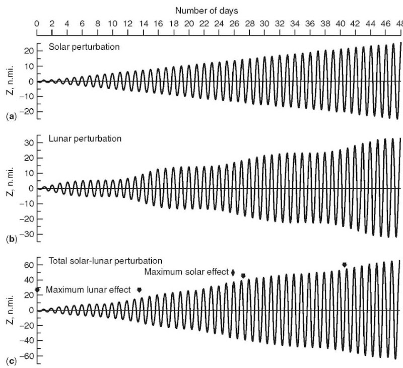
Figure 11. Typical daily longitudinal variations of 24-hour satellites due to solar and lunar perturbations.
Note that Fig. 12 shows variations in satellite orbital inclination at maximum solar-lunar perturbation times. Hence, continuing the indicated thrust schedule will keep the satellite within the bounds shown.
Present Station keeping Systems. A typical layout3 of a contemporary string-redundant ion propulsion system for north-south station keeping maneuvers on geosynchronous satellites is shown in Fig. 13. A single north and south thruster can provide a AVe750m/s required to maintain the orbit of a GEO satellite in the Earth’s equatorial plane for a 15-year period. Two thrusters are powered by a common PPU, minimizing the overall mass of the propulsion system (30). Using this arrangement, voltages are applied simultaneously to the various electrodes (i.e., screen, accelerator, decelerator, anode, and keepers) of the north and south primary thrusters (N1 and S1). However, cathode heater power and xenon gas flow is provided only to the thruster selected for the propulsive maneuver (see the north thruster at the ascending node). Twelve hours later, when the satellite approaches the other nodal crossing, the same PPU applies voltages to the electrodes of the primary thrusters N1 and S1, but gas flow and heater power are provided only to the selected thruster (see the south thruster at the descending node). Full redundancy is achieved by using the other PPU and the secondary thrusters N2 and S2. The two thruster pairs shown in Fig. 13 (a primary and a secondary) are mounted on a motorized platform that can be gimbaled in two axes to maintain the thrust vector pointing through the spacecraft’s center of mass.
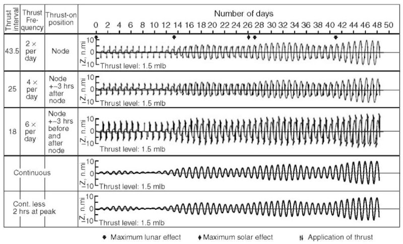
Figure 12. Latitudinal control using various thrust sequences.
The xenon storage and control system typically consists of two xenon tanks isolated by a squib valve and a dual-string arrangement of a squib valve, two-stage pressure regulator, and series-redundant latching valves. The string approach illustrated in Fig. 13 typically uses the primary thrusters for the first half of the mission and the secondary thruster pair for the second half of the mission. If a regulator fails in either leg of the system, the squib valve that normally isolates the two legs is fired so that both tanks can provide xenon to the remaining usable thrusters.
As described earlier north-south station keeping is accomplished by firing a north thruster daily for a period of approximately 5 hours centered about the ascending node. Twelve hours later, the south thruster is fired for the same duration, centered about the descending node. Because the thrusters are typically aimed away from Earth, firing them introduces a radial component of thrust that would normally make the orbit undesirably eccentric. However, this twice-per-day thrusting strategy automatically removes the eccentricity in any 24-hour period. The propulsive maneuvers are directed by the spacecraft’s computer, which follows program commands uploaded to the satellite every two weeks. Interplanetary/Planetary Spacecraft (Prime Propulsion). Figure 14 represents the propulsive requirement for a number of interplanetary/planetary missions as a function of distance from the Sun. The curve labeled minimum energy transfers (Hohmann) describes the velocity increment required for a minimum flyby of a particular body at its position relative to the Sun. These Hohmann transfers for missions to Jupiter and beyond often require prohibitively long flight times.
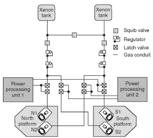
Figure 13. Layout of a modern xenon ion propulsion subsystem.
The horizontal line, labeled chemical limit, describes the maximum velocity-increment, capability assuming chemical propulsion systems and a single Space-Shuttle launch. The velocity increments required for a number ofmissions are overlaid on this figure and expressed both for a chemical-propulsion mode and for an electric-propulsion mode. (The velocity increments required for chemical- and electric-propulsion modes differ due to the gravity loss terms for continuous thrusting during long times). A number of missions are shown that are well within the capabilities of solar-electric propulsion.
Modularization. Relatively speaking, high thrust cannot be provided by a single ion thruster because of technological problems associated with extremely large diameters of discharge chamber and ion optics components. Therefore, modularization of the total thruster system (e.g., see Fig. 15) is required (31). Modularization, however, in a positive sense, leads to two critical propulsion system design advantages: 1) the possibility of increased system reliability through redundancy and 2) the ability to power-match the solar panel power source to the propulsion system’s electrical load.
System Reliability. An important question to be answered before system design can begin is the total number of modules to be employed in building up to a high-power electric propulsion system (32). Several important considerations affect the answer to this question; the foremost is system reliability.
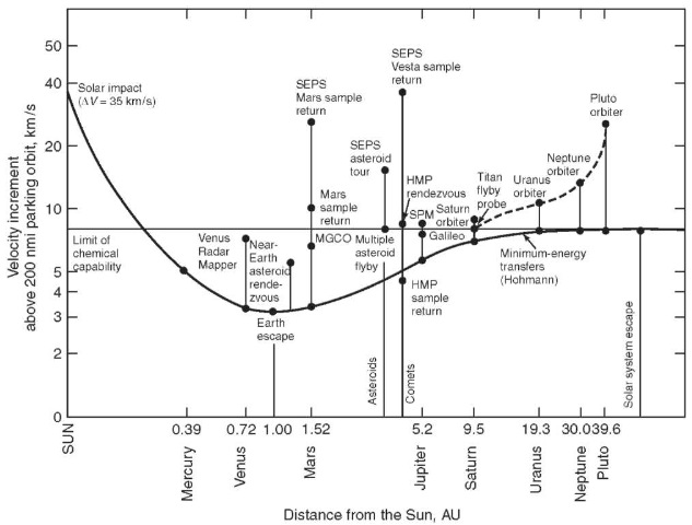
Figure 14. Interplanetary mission propulsion requirements.
As is well known, establishing component reliability figures at high confidence levels requires costly and time-consuming test programs. It is possible, however, to build up system reliability through redundancy techniques even though component reliability is somewhat low or possibly not even established. Redundancy, whether series, parallel, or standby, will increase propulsion system weight. Therefore, it is always desirable, to determine the method by which the requisite reliability can be obtained by adding a minimum to system weight.
Standby redundancy proves especially applicable in the engine and power conditioning systems, provided that each of these systems is composed of a number of identical modules. In addition to incorporating initial standby units in a modularized ion propulsion system, it will be shown in the next section that, because of the decrease in available power and increase in output voltage of the solar panel in deep-space missions, engine and power conditioning modules will be shut down during the course of the mission. In each case, the modules and their respective subsystems will be designed so that disconnected modules can be reconnected. From the view point of reliability, the shutdown modules can be considered standbys.
Power Matching. As mentioned in the previous section, a major challenge in designing a solar electric propulsion system is the use of the maximum power available from the solar panels. The thruster and power conditioning systems must be designed and programmed to provide the proper load at all times to the constantly varying power and voltage outputs of the solar array. Figure 16 shows a family of normalized nonlinear I-V characteristics for a solar panel on a trajectory directed toward the outer reaches of the solar system. This example assumes a modularized ion engine system that begins the mission by using 16 modules at full thrust and, as solar panel power decreases, engines are switched off at the appropriate times to maximize power transfer from panel to engine load (33).
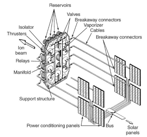
Figure 15. Conceptual drawing of a 48-kW ion propulsion system.
At any particular time during the example mission, the system must operate at a point located somewhere on the I-V curve, which corresponds to that time. For each I-V curve, a point [I(t), V(t)] can be found at which the power (P = IV) is a maximum. To operate at the point [I(t), V(t)] and thereby derive the maximum power possible from the solar panel at time t, the resistance of the load RL must be matched to that of the source [i.e., RL = R(t) = V(t)/I(t)].
Maximum power is transferred from the solar cell source when the load resistance is equal to the source resistance of the solar cell supply. Because of the motion of the solar cell array away from the Sun, its I-V characteristics will vary with time during the mission. Therefore, its source resistance R will be a function of time and actually will increase during flight away from the Sun. If the load is thought of as a constant-current device, its resistance can be increased to follow R(t)in two ways:(1) the propellant flow rate (and, thus, the beam current) can be decreased continuously so that the R(t) curve is followed identically, or (2)single engines of the modularized thruster system can be switched off at appropriate times to maintain the load resistance close to R(t). If Mp (propellant flow rate) is adjusted continuously during the mission, the load resistance will always be matched to R(t), and maximum power transfer will be maintained. In this case, the current in each engine system must be capable of varying 60% during the mission, and the engine voltage will have increased 17% at the end of the mission. Operation across this range of beam current and voltage is, at best, undesirable from the standpoint of ion engine design. However, switching engines and power conditioning inverter modules off and returning all of the remaining modules to full thrust conditions can reduce these required operating ranges to 10% or less. This level of variation is well within the capability of present day ion propulsion systems.
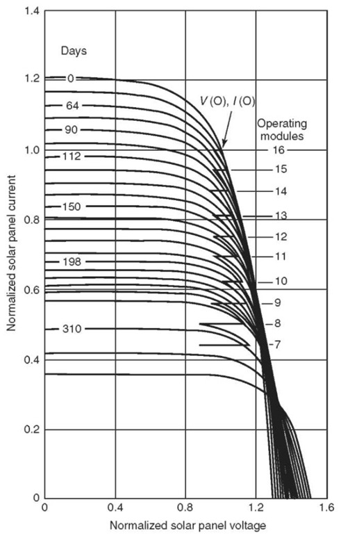
Figure 16. Normalized solar panel I—V characteristics for example trajectory away from the Sun.
Early Mission and Spacecraft Designs. The initial (e.g., late 1960s to 1970s) design philosophy adopted for the general arrangements of the solar-powered electric-propulsion spacecraft was one in which designs 1) were formulated to be adaptable to as wide a variety of interplanetary missions as possible for a specific launch vehicle and 2) could scaled to be compatible with a variety of existing NASA family launch vehicles. This concept was achievable by modular design of the electric-propulsion system that allowed using of the same thruster and power-conditioning system modular designs, in varying numbers, to accomplish a variety of missions with various launch vehicles.
During these early studies, for example, two baseline conceptual spacecraft designs were primarily considered. One was a spacecraft suitable for a Mars orbiter and lander mission launched by Titan III-M with a hammerhead shroud, and the other was a universal spacecraft for a Jupiter flyby or out-of-the-ecliptic mission launched by an Atlas SLV-3C/Centaur with a newly modified shroud (34). The power level required at 1 AU for the ion propulsion systems for the two baseline designs was established as 9.6 kW for the Mars mission using the Titan III-M launch vehicle and 17 kW for the Jupiter flyby and out-of-the-ecliptic missions using the Atlas SLV-3C/Centaur launch vehicle.
Even though technological advancements and identification of new spacecraft concepts will continue, the conceptual bases of these designs still demonstrate the propulsion system elements for developing future high-power solar-electric propulsion of interplanetary/planetary spacecraft. They also demonstrate and emphasize the intimate design aspects of solar-electric propulsion and its host spacecraft.
Mars Mission Spacecraft. A conceptual spacecraft design was developed for the 9.6-kW power level Mars orbiter and lander mission using the Titan III-M hammerhead shroud configuration and a folding modular-type solar array (see Fig. 17). The solar panels are deployed in a plane normal to the spacecraft’s longitudinal axis into the four quadrants at the base of the spacecraft bus. A total of 20 rectangular subpanels of equal size (8 x 7 feet) are used to provide a gross area of 1120 square feet. To provide adequate thruster exhaust beam clearance for the solar array, the outboard auxiliary subpanels have been hinged to deploy asymmetrically, eliminating impingement of the exhaust flux on the panels. The main hinge attachment of the solar array to the spacecraft is at the base of the spacecraft bus. The spacecraft longitudinal axis is along the sun-probe line, and the solar cells are placed on the surface away from the spacecraft bus. In this manner, the entire spacecraft bus remains in the shade, thereby relaxing thermal control requirements. The solar array subpanels are purposely limited to 8 feet in length, so that they do not extend forward (in the stowed configuration) beyond the cylindrical portion of the hammerhead shroud. By preserving shroud stowage volume forward of the cylindrical section, various lander shapes, whose maximum diameters are up to approximately 11 feet, may be accommodated. The Apollo-type lander capsule depicted here is 8 feet in diameter.
In the four-quadrant solar array configuration, the panels are stowed in a box-like fashion around the cylindrical spacecraft bus, limiting the bus to a 7-foot-diameter cross section. The spacecraft’s cylindrical structure is locally squared off to accommodate the electric engine array. Placement of the engine array external to the basic spacecraft frame and shell permits greater freedom for thruster array translational motion and thrust vector angular motions, which may be desirable for some missions.
Power-conditioning modules are attached to the spacecraft bus on each side of the engine an dare in shade cast by the primary solar panels. The high-ainan-tenna is stowed within the base of the spacecraft bus and gimbal-mounted to satisfy clock and cone angle requirements for Earth communications. A 7-foot-diameter planar array antenna is indicated, although a 1-foot increase in diameter may be incorporated within the constraints imposed by the launch-vehicle geometry.
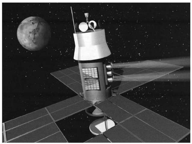
Figure 17. Titan III-M SEP Spacecraft in transit to Mars.
Major subsystems such as the nitrogen gas tanks for attitude control, bus or body-fixed scientific payload, communication electronics, and guidance and control equipment are housed within the spacecraft bus frame. The temperature of the spacecraft is controlled by two sensor-actuated louver systems.
The spacecraft bus, including the lander capsule, is to be retromaneuvered into the orbit of Mars by a liquid chemical rocket. All spacecraft configurations designed for missions presented here assume that a liquid bipropellant retro-rocket subsystem is used. The systems have been sized for a specific impulse of 315 s for a liquid bipropellant thruster that uses MMH fuel and N2O4 oxidizer. The retrorocket and tankage are mounted so that the thrust vector is directed along the spacecraft’s longitudinal axis. The four solar panels beyond the outboard hinge of the primary panels are separated and ejected radially away from the spacecraft before the retromaneuver.
The planet-scanning scientific equipment is mounted to deploy into the space between two adjacent solar panel assemblies on the opposite side of the thruster array to obtain maximum unobstructed viewing. Two low-gain omnidirectional antennae are indicated. They are located on the spacecraft where they do not depend on deploying any other subsystem before they operate normally. The primary low-gain antenna is deployed out of the base after spacecraft/ launch-vehicle separation.
The attitude control nitrogen storage tanks are mounted symmetrically about the center of mass of the deployed spacecraft configuration so that they do not contribute to center of gravity displacement as gas is consumed throughout the mission. The attitude control thrusters are located at the outer edge of the four innermost solar panels. The retrorocket fuel and oxidizer tanks are located symmetrically about the retrothrust chamber.
Jupiter Mission Spacecraft. The ion propulsion module used for the Mars spacecraft can be adapted to a mission to Jupiter. The selected mission requires an ion engine system rated at 17 kW at 1AU. The Mars spacecraft previously considered imposed major design considerations dictated by the mission profile. The same is true of the Jupiter mission. Of primary concern was the large dynamic thermal range introduced by the large temperature range encountered on a Jupiter mission trajectory. For reasons of thermal control, the spacecraft bus was placed on the shadow side of the solar array plane. Maximizing the size of the high-gain antenna (6-foot-diameter parabolic dish) negated the feasibility of stowage within the base of the spacecraft due to the space limitations imposed by the package envelope of the solar array and the 57-inch launch vehicle interface. In lieu of a circular parabolic dish, a highly elliptical dish is also considered and stowed longitudinally within the spacecraft so it can be deployed out of the base. This design was rejected due to the articulation required for deployment, plus the large volume required for stowage.
The only space solely restricted by the launch-vehicle shroud envelope that is void of spacecraft interface considerations exists at the top of the spacecraft. The main solar panel hinges and high-gain antenna are placed at the top of the spacecraft bus, thereby satisfying both thermal control and communications considerations and eliminating the requirement that the high-gain antenna be articulately deployed using a mast and associated mast-mounted pointing actuators. Placing the power-conditioning modules remotely from the solar panels significantly reduces thermal coupling.
Adequate area exists in the base structure of the spacecraft to accommodate two of the six power-conditioning panels with an unobstructed view for radiating to space. For spacecraft mass balance and thermal isolation, the bulk of the spacecraft electronics and scientific payload is situated in a compartment adjacent to the power-conditioning equipment. The equipment in this compartment is thermally controlled by an independently active louver system.
Two low-gain antennas are deployed from the spacecraft bus, one to the normal sun-side position and one to the shadow side from the base of the spacecraft. Deploying either low-gain antenna is not contingent on deploying any other spacecraft subsystem. A medium-gain horn is mounted on top of the feed-supporting tripod of the high-gain dish antenna.
The ion propulsion system is composed of eight thrusters, six propellant tanks, and associated control and switching components. The thruster array is placed so that the exhaust beam is directed between two adjacent solar panel assemblies. The engine cluster is fixed so that its thrust vector is directed 90° to the Sun line. To accommodate the exhaust beam divergence of the ion thrusters without exhaust impinging on the outboard solar panels, the auxiliary subpanels are, as in the spacecraft previously discussed, asymmetrically hinged to provide maximum clearance in the thruster quadrant. To maintain symmetrical area distribution, the panels on the side opposite the engine are arranged likewise.
The major portion of the spacecraft base is enclosed for thermal control. The central and upper sections of the spacecraft are purposely void of equipment because the most effective location for compensating for the weight of solar panels is at the base (bottom end) of the spacecraft. The attitude control nitrogen gas tank is mounted within the equipment enclosure, and the attitude control thrusters are mounted on the outboard edge of each of the four solar panel assemblies.
A truss structure extends upward to provide a square framework at the top for the main hinge attachment of the four solar panel assemblies. A light tripod supports the high-gain antenna and pointing actuators on top of the solar panel hinge frame. The truss structure in the vicinity of the engine cluster is constructed to allow longitudinal and lateral translation of the entire engine system.
Out-of-Ecliptic Probe. The out-of-ecliptic probe uses the same spacecraft (with minor modifications) as that considered for the Jupiter flyby mission. Although thermal considerations and communications requirements for an out-of-ecliptic probe do not pose design constraints as severe as those for the Jupiter flyby spacecraft, the spacecraft arrangement developed for the Jupiter mission is well suited to serve as an out-of-ecliptic probe with only minor modifications. For communications, only low-gain antennae are required. The sun-side low-gain antenna need not be deployed as on the Jupiter spacecraft, but may be permanently mounted on top of the spacecraft, simplifying the antenna mount design. For an out-of-ecliptic spacecraft, the space previously used by the high-gain antenna for a Jupiter mission may be used to accommodate approximately 25 square feet of fixed solar cell panels.
Present Deep Space Systems. NASA’s NSTAR ion propulsion system consists of a 30-cm-diameter thruster, PPU, digital control interface unit (DCIU), and xenon feed system (XFS). Responding to commands received from the DCIU, the PPU can operate the thruster at any one of 16 power (thrust) levels, ranging from 500 W to 2.3 kW. (producing 19.5 to 92 mN of thrust). This wide range of power throttling enables the NSTAR thrust system to match its performance to the power available from the host spacecraft. To optimize the thruster performance across such a wide range of power throttling, the XFS adjusts the xenon flow rate to the cathodes and the ionization chamber to match the values stored in the DCIU memory. This feature adds some complexity to the XFS, but it also ensures that the thruster operates at the proper conditions to maximize performance and lifetime across the entire power range.
Conclusion
To the young scientists and engineers interested in the technological progression of humankind, we would like to use our experience in developing ion propulsion to make a point. During the 40-year research and development and eventual application of ion propulsion, there were many doubters, critics, and cynics who made known their disbelief in the efficacy of this technology! They expressed their disbelief by conjuring up the phrase, Ion propulsion is the technology of the future and always will be! Our response now is the obvious statement,Perseverance pays off! A corollary: If you believe in what you are doing and in yourself, do not give up even in the midst of strong criticism by your detractors!
Technological Spin-offs. Ion thrusters and their associated expellant and electronics subsystems have been under development for more than four decades. During this time, numerous approaches to creating and accelerating ions for spacecraft propulsion have been investigated. Obviously, during these many years and substantial government and industrial expenditures, an extensive technological base has been established. In fact, during the evolution of these basic ion thruster technologies, the development of ion and plasma devices for a number of important nonpropulsive applications was initiated. Among these applications are some of the most advanced and critical modern semiconductor device fabricating techniques such as ion implantation and ion beam sputtering. In addition, and also of importance, are the following: (1) the advancement of secondary ion mass spectrometry, (2) the creation of spacecraft potential control, (3) the invention of a new family of power converter and switch tubes, and (4) the development of effective neutral beam injectors for fusion reactors. All of these ion propulsion technological spin-offs are more fully described in Reference 36, along with many additional specific references.
