Plasma thrusters are a class of electric propulsion in which the working medium has the form of plasma in the acceleration zone. The presence of plasma, both positive ions and negatively charged electrons, in the acceleration gap distinguishes plasma thrusters from ion thrusters where the acceleration gaps contain only positively charged ions. In ion propulsion, the space charge field restricts the emissions of ions from the emitter (ion generator), and thus ion thrusters have a relatively low thrust density and require a high acceleration voltage. As a result, they can be efficient only with an acceleration voltage > 1 kV and exhaust velocities of >30km/s.
Because the acceleration gaps in a plasma thruster contain both positive ions and electrons, no space charge is needed. For this reason, there are no limitations in theory on the thrust density in plasma thrusters, and the exhaust velocity may range from a few km/s to hundreds or more km/s. Of course, different plasma thruster designs are optimal for each range of exhaust velocities and power levels.
Plasma thrusters, like other electric propulsion thrusters, are of interest for space technology primarily because of their capacity to reach high exhaust velocities, greater than those attained by thermochemical (liquid or solid) fuel rocket engines. In a number of instances, other features of such thrusters may also be of interest.
The chemical energy contained in the working medium is not sufficient to attain high velocities. For this reason, plasma thrusters, like other rocket engines, require special sources of energy. Today, these sources may be either the Sun or nuclear processes of one kind or another (fission, radioactive decay). For each specific flight, optimal velocity parameters exist, defined with respect to minimum total mass of propellant and power source. The optimal exhaust velocities for the majority of purposes are currently within the range of approximately 15-30 km/s.
On the Classification of Plasma Thrusters
These thrusters are classified primarily on the basis of the mechanism for’accelerating the plasma. Here, we identify three basic types of plasma thrusters.
• Thermal plasma thrusters in which the electroconductive plasma is heated to high temperatures (>3000°C) by a current passing through it and then is exhausted from the thrusters. Depending on conditions, the positive ions and electrons may be heated at the same time (isothermic plasma thrusters), or predominantly electrons will be heated (nonisothermic plasma thrusters).
* Electromagnetic (Ampere’s force) plasma thrusters, in which the plasma is accelerated by Ampere’s force:

where F is measured in newtons, B is magnetic induction in teslas, J is current in amperes, and l is the length of the current lines in the accelerated plasma.
Because of the limits on power sources in space, the plasma thrusters of today, are developed to generate ones, tens, and hundreds of grams of thrust, although, as noted before, there are theoretically no limits on the amount of thrust that can be created by a single module.
Clearly, the acceleration of conducting plasma by Ampere’s force is analogous in nature to the operation of various electric motors. However, in plasma thrusters, the plasma is not accelerated through rotation, but driven in a line, as in linear electric thrusters. Thermal effects in such plasma thrusters have only a slight effect on thrust. It is noteworthy that in the midnineteenth century, Maxwell demonstrated that the effect of Ampere’s force may be treated as the pressure of a magnetic field.1
* Finally, the third class encompasses plasma thrusters in which acceleration is achieved through both kinetic gas pressure and Ampere’s force.
The division of plasma thrusters into three groups on the basis of the acceleration mechanism is very general. However, detailed classification of all possible plasma thrusters on the basis of their physical or design features is virtually impossible,and we will not attempt to do so here. Instead, we will describe only representatives of the three types of plasma thrusters that have already functioned in space. We will not touch on electrically heated thrusters with low exhaust velocities.
Aside from the three types previously noted, we will describe two more promising candidates for future plasma thrusters and their “progenitor.” Ampere’s force generally plays the decisive role in these thruster types. Pulsed Plasma Thrusters (PPT). PPTs were the first plasma thrusters used for spaceflight (in 1964 on the Zond-2 spacecraft). There are two reasons that the PPT was the first type of plasma thruster to operate in space. First, because prototypes existed, specifically impulse accelerators (“guns”), which first made it possible to produce plasmoids at velocities of many tens of km/s. The second reason was the simplicity of the PPT propulsion system.
Principles Underlying the PPT. The simplest (from the theoretical standpoint) PPT design is the “railvestron” that has an external magnetic field. This device consists of two rails placed inside an external magnetic field and connected to a power source (Fig. 1a). If the rails are linked by a movable conductive cross-connecting jumper, then current enters the circuit, and under the influence of Ampere’s force, the jumper begins to accelerate.
The accelerator described may be simplified if discharge currents are large (and thus pulses are short). In this case, the device does not need an external magnetic field and runs on the intrinsic magnetic field of the circuit. Such systems have been used to generate plasmoid velocities approaching 100 km/s. However, one complex element still remains in this design, the valve that feeds gas between the rails, whose breakdown creates the necessary plasma connection.
The Bostich (1953) plasma was generated by ablation (destruction and evaporation) of an insulator that separates the electrodes. For this reason, the use of gas valves was rejected fairly early, and PPT virtually always used ablation of one or another insulator, for example, Teflon. Thus, we will deal in what follows only with ablative pulsed plasma thrusters (APPT). Each APPT has two electric circuits: the circuit for igniting the discharge and the main discharge circuit. Ignition of the main discharge uses a small amount of plasma, which is formed, for example, by passing a pulsed current through a contact between the corundum rail and a copper plate. This initiating stage may be located at various points, for example, inside the central electrode, as depicted in Fig. 1b. Plasma enters the main discharge gap through slits in the electrode and induces a discharge close to the insulator, thus causing it to erode. The resulting products of its decomposition are ionized and begin to accelerate because of Ampere’s forces, as well as kinetic gas pressure.
APPT Designs. APPT designs differ depending on the thruster’s purpose. The coaxial design portrayed in Fig. 1b is intended for use with relatively high power (>100 joule). For low power (<100 J), the preference is for a flat rail design, which was first used on the United States LES-6 satellite (Fig. 1c). Finally, if it is desired to obtain the largest possible impulse for a given power, it is necessary to decrease the exhaust velocity and increase the mass flow rate, that is, switch from an electrodynamic to an electrothermal mode at exhaust velocities of approximately 3-4 km/s. Such a “closed” APPT model was used on Zond-2 (Fig. 1d). Note that two-stage APPT engines have also been developed.
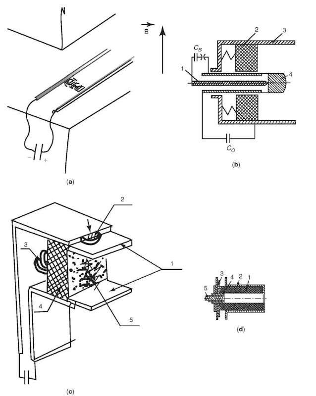
Figure 1. Schematic diagrams of different types of APPTs: (a) railvestron with external magnetic field; (b) coaxial electrodynamic APPT: (1) ignition needle, (2) dielectric, (3, 4) main electrodes; (c) rail type APPT: (1) electrodes; (2) main discharge initiator; (3) spring releasing the dielectric; (4) dielectric; (5) streamer inducing the main discharge; (d) electrothermal coaxial APPT: (1) dielectrics; (2) external electrode; (3) internal electrode; (4) insulator; (5) ignition electrode (Zond-2 spacecraft).
APPT Mode of Operation. Unlike in gas PPTs, in which a previously created cross-connecting jumper is used to provide acceleration, in APPTs during the discharge process and partially after its termination, substances are emitted constantly from the insulator. For this reason, simulation of flow in the APPT requires a hydrodynamic description that takes into account the diverse processes of the ablation of insulators.
Without going into a description of the entire process of discharge in an APPT, we will note the properties of insulator erosion. After breakdown induced by the initiative plasma, the material of the insulator begins to participate in the discharge. This ablation primarily occurs through radiation of plasma, and its intensity correlates well with the momentary power of the discharge. Using small expenditures of energy (Wc< 100 J), the erosion mass increases as a linear function of Wc, and at high energy expenditure, the erosion mass is proportional to Wf. Here Wc is the energy stored in the condensers.
The performance of an APPT increases as the energy expenditure increases in a single pulse. This pertains both to the exhaust velocity, which attains many tens of km/s, as well as to the efficiency coefficient, which reaches several tens of percent at energy expenditures > 100 Joules. Fig. 2 shows how a single impulse depends on energy expenditure in various models.
The factors that restrict the efficiency of an APPT are change in the discharge current over time and vaporization of the insulator at small discharge currents, in which the plasma does not attain the necessary velocity. Discharge nonstationarity depends on correct selection of the insulator material. Insulators made of Teflon have proved to be quite good.
The First APPT Spaceflight. The first flight took place in Russia. Work on pulsed plasma thrust at the Atomic Energy Institute (AEI)2 began in late 1960, and by 1961, efforts were already concentrated on ablative pulsed plasma modules. Development work was conducted under the direction of A.M. Andria-nov. They developed thrusters with various parameters, including sustainer thrusters for interplanetary flight. In late 1961, contacts were established with the S.P. Korolev Design Bureau, which proposed to develop an electrothermal APPT for the planned Zond-2 spacecraft. Figure 3 shows an electrothermal propulsion system with an APPT (developed with the collaboration of V.A. Khrabrov), which was used for the attitude control system on the Zond-2 interplanetary probe. After initialization of discharge, gas heated to a temperature of approximately 5000°C was exhausted at a velocity of approximately 2-4 km/s, imparting the corresponding impulse to the thruster.
The parameters of this propulsion system with 6 APPTs are as follows: energy stored in the condensers - 56 Joules; operating frequency – 1 Hz; single pulsed thrust – 2 x 10 ~ 3 N-s, total thrust impulse – 7.2 x 10³ N-s thrust efficiency – ~ 6%; working medium supply – 3 kg; mass of the propulsion system – 28.5 kg; service life – 5 x 10⁵ impulses.
This system was turned on at a distance of ~ 1 million km, and thus did not run very long. However, all at the parameters listed here were confirmed during ground tests.
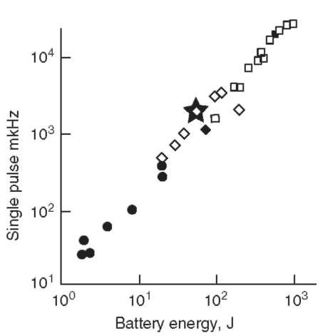
Figure 2. A single pulse (mKNs) as a function of battery power.
Subsequent APPT Development. In the West, the first APPT launch occurred in 1968 for station keeping of the US stationary communications satellite LES-6. It was developed by the MIT Lincoln Laboratory. The energy expenditure on discharge was ~2 joules. The specific impulse was 250-500 s. The mode of operation was almost thermal, and the system functioned for approximately 10 years.
On the LES-8/9 satellite launched by the United States in 1973, the energy expenditure on discharge reached 80 joules. The maximum specific impulse was 1450 s. Thirty mg of insulator was vaporized on one impulse. This APPT operated in a purely electrodynamic mode.
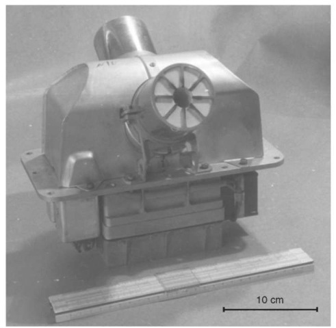
Figure 3. APPT for the Zond-2 spacecraft.
There are two more APPT spaceflights that are noteworthy. In 1981 China launched MDT-2A. Here, the energy expenditure on an impulse was Wc = 23.9 joules. The maximum specific impulse lasted 990 s. Finally, in the fall of 2000, the United States launched the EO-1 satellite containing an APPT. The energy expenditure on an impulse was ~60 joules, the specific impulse was ~ 1000 s. The efficiency was ~20% at an energy expenditure of up to 100 joules per impulse. The total mass of the system was 31 kg, of which 12kg was the insulator, that is, the working medium. This propulsion system was still operating in the fall of 2001.
Future Prospects for APPT. Various APPT models developed in laboratories had a service life of 107 impulses and a total impulse of 105 N-s. The energy in one discharge ranges from fewer than 10 joules to thousands of joules. The specific impulse increases with discharge energy and reaches 2500 s at an energy expenditure of 200-300 joules.
Interest in such thrusters waxes and wanes, and it is highly likely that with time they will occupy a reliable ecological niche. This optimistic opinion can be justified by three unique (at least at the present) properties of pulsed propulsion systems:
• They do not require preparation time to start operating.
• There are no valves in the erosion version.
• They can generate small impulses (~ 10 ~5 N-s), which is important for precise attitude control of a spacecraft.
Today an additional argument in favor of APPT is the continually increasing interest in small satellites.
Not even considering future APPTs, we must bear in mind that, from the standpoint of minimal impulse (~10~3N-s) and high efficiency (~>40%), a stationary plasma thruster (SPT) operating in a quasi-stationary mode may be useful. But SPTs require a preparation period before they can start operating (~1 minute) and have valves.
Stationary Plasma Thrusters (SPT). After the APPTs, the next PTs that were launched into space (in 1971) were stationary plasma thrusters. These plasma thrusters operated or currently operate on more than 60 satellites. We will concentrate on them for this reason. First, we will provide a brieftheoretical introduction.
On the Dynamics of Particles in Electromagnetic Fields. SPTs are plasma thrusters, and thus their operation can be described using formula 1 for Ampere’s force and the so-called generalized Ohm’s law, considering also the Hall effect. However, the operation of SPTs is more clearly described using the language of electron and ion dynamics.
Several general factors are noteworthy. In the absence of an electric field and at a constant value of B in space and in time, the general motion of particles takes the form of a helix, which can be considered a superposition of two motions: along B with a constant velocity component Vn and revolution around a circumference in a plane perpendicular to B at an angular frequency of wH and radius pH:

This frequency and radius are called, respectively, the Larmor or cyclotron frequency and radius. If, aside from the homogeneous and constant field B, there is another homogeneous and constant electric field perpendicular to B, then a more complex motion is generated, which can be considered the superposition of the helical motion described and motion in a direction perpendicular to E and B at constant velocity,

which is called ”electron drift velocity.” The perpendicular electric current that is thus generated is often called a Hall current. The current along the E field (the usual Ohm current) is virtually absent under these conditions. However, this happens only in the absence of collisions with heavy particles. When these particles collide, the electron loses its drift velocity and to gain speed again under the influence of the E field, it is displaced toward the anode. This generates an Ohm current. Its magnitude depends on the frequency of collision, or to be more precise, on the product of the Larmor frequency wH and the free path time t. The physics of SPT — its plasma dynamics for coeTe 1. For this reason, SPTs are frequently called Hall accelerators.
Equipotentialization of Magnetic Force Lines. Electrons can freely move along force lines, and this leads to a situation where in plasma, the force lines ofa magnetic flux with accuracy up to comparatively weak thermal disturbances become equipotential. For this reason, force lines with superimposed helical electron trajectories can be considered transparent magnetic electrodes, moving at drift velocity. In other words, we can coin the term ”electromagnetic electrodes.”
Now let us return to the SPT.
SPT Design. SPTs are depicted in Fig. 4a. Here, we distinguish three modules:
1. a magnetic system consisting of a magnetic conductor (1a), axial symmetrical poles (1b), and a magnetization coil (1c), generating a quasi-radial magnetic field in the channel;
2. a gas-plasma loop, consisting of the gas tube (2a), a gas distributor (2b), a buffer volume (2c), and an axially symmetrical dielectric channel (2d);
3. an electric discharge circuit, including an electron receiver anode (3a), a power source (3b), and a thermocathode electron emitter (3c).
The magnetic system generates a quasi-radial magnetic field, increasing as it approaches the end of the accelerator. The force lines of this field are convex toward the anode (Fig. 4b). The magnitude of this field is selected so that the electronic Larmor radius pe is much less than L, the length of the discharge gap, and the ion radius pi is much greater than L because the ions are virtually unaffected by the magnetic field:

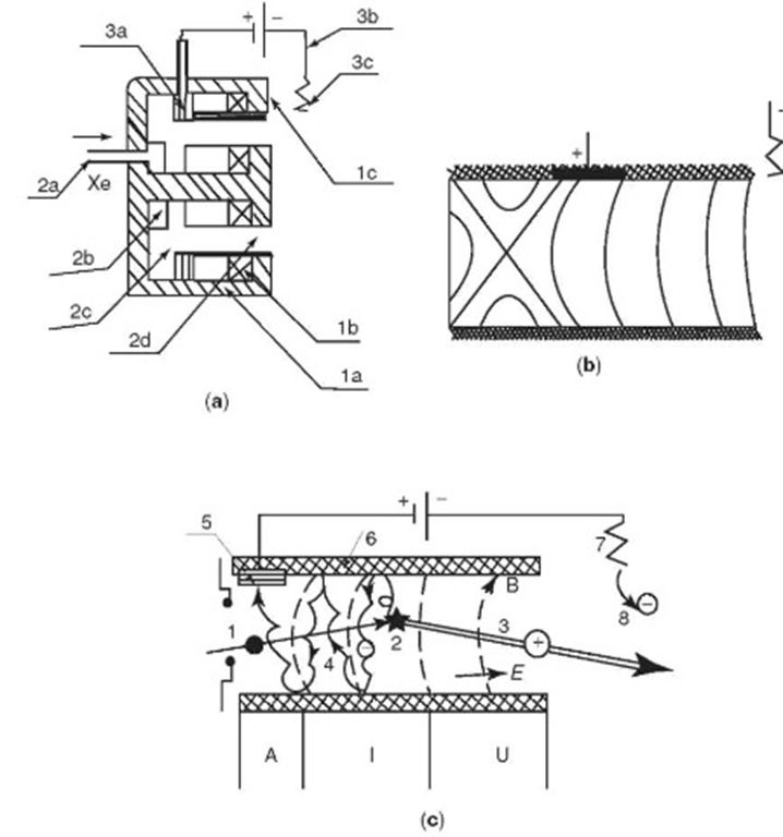
Figure 4. (a) SPT design (explanation in text). (b) The nature of magnetic force lines in the SPT channel. (c) Functional design of an SPT: (1) neutral atom; (2) its ionization; (3) the current that has been generated is accelerated by the electric field; (4) the free electron forming during ionization diffuses on the anode; (5) the anode; (6) the walls of the channel; (7) thermal cathode; (8) electron emitted by cathode; A- anode zone.
In actuality, today we are discussing magnetic fields at a maximum of ~(1.5-3) x 10 ~ 2T, and channel length of ~2-3 cm. When the magnetic field increases as it approaches the end, the plasma configuration is macrostable (for more information, see the next section), and thus a rather stable distribution of the electric field forms in the channel. The voltage of the longitudinal electric field in the main part of the channel is proportional to the magnitude of the radial magnetic field component.
The Functional Design of the SPT. Because of the presence of mutually perpendicular E and H fields, the electrons drift along the azimuth, creating an azimuthal current. Its interaction with the radial magnetic field generates Ampere’s force. The presence of azimuthal drift in this model involves ”the rotation of the whole system of electromagnetic electrodes (Fig. 4c).”
Neutral atoms emitted from the gas distributor are caught up in the rotating cloud of electrons and are ionized there not far from the anode (Fig. 4c). Because the density of the neutral atoms in this zone is ~3 x 1013cm ~ 3 and the ion density is ~1012cm ~3, collisions among atoms and ions are negligible, but this is not true of their collisions with electrons. For this reason, if an ion generated at a point of potential F* does not collide with the walls and is not ionized a second time, it accelerates under the influence of the E field and leaves the channel with energy
![]()
Experiments have shown that the mean energy of the ion in the exhaust is
![]()
where Up is the difference in potential between the anode and the cathode. The degree of ionization of the flux of xenon atoms, which today is the main working fluid in the SPT channel is very high, ~95%. The effective thickness of the ionization zone is ~ 4-5 mm. Although the electrons that form during ionization appear in the magnetic field, they must hit the anode. There are several factors that facilitate this. Having reached the anode one way or another, the electrons then pass through the external circuit and are emitted from the cathode in the ion flux that is exhausted from the SPT channel, providing ”spatial,” and also ”current” neutralization of the ion flux.
The discharge current is a relatively accurate function of mass output. The volt-ampere characteristics in Fig. 5 frequently point to saturation of the discharge current for a given output m. Typical values for the thrust efficiency coefficient (taking into account loss in the magnetic system and cathode) are of the order of 50-65%.
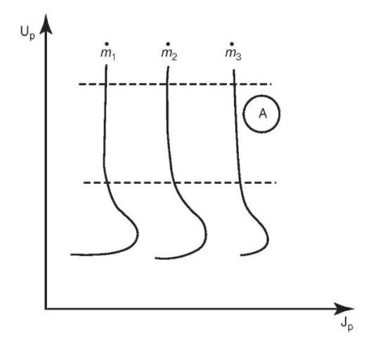
Figure 5. Schematic graph of volt-ampere characteristics for various mass expenditures (m3>m2>m1).
Characteristics of the Physical Process in the SPT. From the standpoint of physics, an SPT is a completely new type of gas discharge system, which is unlike all other classic or new discharge devices. We will discuss two theoretically important points: the macrostability of the plasma configuration and the role of electron collisions with the dielectric walls of the channel.
On Discharge Stability in an SPT. For almost 50 years, no one succeeded in generating a superheated electric field in a well-ionized plasma using a magnetic field. As a result, it was concluded that this was impossible (the ”Baum barrier”). But the developers of the SPT succeeded in overcoming the Baum barrier by suppressing the large-scale azimuthal nonsymmetrical instability, the so-called ”spike,” which had been short circuiting the anode and the cathode within the SPT channel. Later, A.I. Morozov proved that the ”spike” disappears if the induction of the magnetic field increases from the anode to the outlet. Specifically the magnetic field that increases as it approaches the outlet is incorporated in the concept of the SPT (see Fig. 4b).
On the Role of Electron Collisions with the Walls of the SPT Channel. SPTs are characterized by high length of free electron paths, the presence of magnetic force lines abutting the channel walls, the presence in the space of a longitudinal electric field, and a high electron temperature (Te>15eV). The combination of these factors gives rise to a series of specific phenomena:
1. The distribution of electrons in the circuit is, in principle, not Maxwellian.
2. The dispersion of electrons on the walls leads to additional transfer of electrons transverse to the magnetic field—this is called ”wall conductivity.”
3. The first experiments showed that the parts of the insulator that adjoined the outlet underwent disintegration because of ion bombardment, which limited the working life of the thruster. Later, during long-term service life tests (> 1000 hours) of the SPT in the Fakel Design Bureau (Kaliningrad), a new form of erosion was discovered. A periodic structure was formed in the insulator, oriented not at right angles to, but along the ion flux (Fig. 8a). The period was of the order of the length of an electron Larmor radius. Evidently, electrons play an important role here; electron impacts on the insulator in one way or another cause it to ”disassociate” and isolate individual atoms or small clusters.
The EOL Propulsion System. The idea for an SPT as a system with a strong superheated volume electrostatic field began to be formulated in 19621963. By the end of 1963, a study of the first SPT model was started in the laboratory of A.I. Morozov and G.Ya. Shchepkin at the AEI in the department headed by L.A. Artsimovich. By mid-1970 a full-scale mockup of the EOL propulsion system containing an SPT had been builthere. Subsequently, it was transferred to the Fakel Design Bureau in Kaliningrad, where the team of Chief Designer, R.K. Snarskiy brought it up to the necessary level; by late 1971, it had been installed in the Meteor satellite.
The propulsion system’s major parameters are as follows:
• propulsion system power ~ 400 W
• thrust ~0.02N
• mass ~18kg.
The design of the EOL SPT is depicted in Fig. 6. On 19 December 1971, the Meteor satellite was launched into space.
At the start of 1972, the EOL propulsion system with an SPT passed performance tests. The main results were
1. demonstration of the reliability of the EOL propulsion system with an SPT and of its compatibility with the satellite;
2. no significant effect of plasma structures on communications with Earth;
3. good correspondence between thrust characteristics measured on the test stand and those derived from changes in satellite trajectory. Instead of the announced working life of 100 hours, the EOL system operated for ~ 150 hours, used its entire supply of xenon, and provided useful correction of the satellite orbit, putting it into a conditionally synchronous orbit, and raising the orbit’s altitude by 15 km.
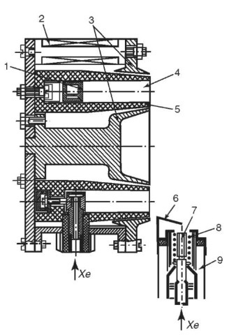
Figure 6. Diagram of the first SPT (SPT EOL): (1) anode; (2) magnetic coils; (3) magnet poles; (4) acceleration channel; (5) insulator; (6) shielded electrode; (7) cathode made of LaBb; (8) start-up heater; (9) cathode-compensator housing.
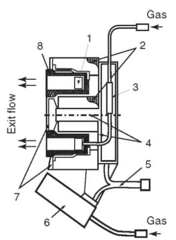
Figure 7. Diagram of the SPT M-100: (1) anode; (2) magnetizing coil; (3) electric isolator in the gas loop; (4) magnetic circuit; (5) electric cable; (6) cathode; (7) magnetic poles; (8) discharge chamber.
Thus, the Fakel Design Bureau had been provided with a useful design for an electric propulsion thruster. As a result, the Design Bureau has been producing propulsion systems with SPTs for more than 30 years. The EOL SPT had an efficiency coefficient of ~35%. Soon after the launch of EOL-1, the AEI proved that the efficiency could be increased significantly (to ~ 50%), if there were a shift to “thin” pole strips, that is, if the gradient (H) along the length of the chamber were increased. This was implemented on the EOL-2 propulsion system.
Further Work on SPTs at the Fakel Design Bureau. Further work involved continuing to improve the design of SPTs, as well as correcting the geometry of the magnetic field. The latter fostered improved stability of SPT operation on the test stand but did not increase its efficiency or lead to diminished divergence of the flux (aeff~ ±45°). One of the main ideas that guided the developers of this magnetic system was the desire to displace the acceleration zone maximally to the end of the channel, which lowered efficiency and increased (or in the best case failed to decrease) the angle of divergence.
Nevertheless, in the late 1970s, the Fakel Design Bureau, collaborating with the Moscow Aviation Institute, developed a standard module SPT M-70.3 Its rated power was ~ 1 kW, thrust ~4g and efficiency 45-50%. The M-70 SPT was installed on nearly 40 satellites.
In the early 1990s, development of a new thruster, the SPT M-100, began. Its rated power was ~ 1.5-2 kW. It was close in design to M-70, but the M-100 had a thicker insulator near the outlet. A schematic drawing of the thruster is provided in Fig. 7. Its external appearance before starting to operate is shown in Fig. 8a and after 5000 hours in Fig. 8b. The performance characteristics of this model are provided in Fig. 8c. The working voltage for the M-100 is ~250-400 V, the thrust is 6-10 g, the efficiency is ~50%, and the flux divergence is
![]()
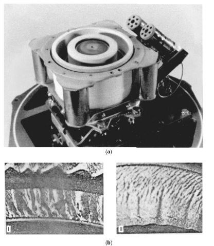
Figure 8. (a) Exterior view of the SPT M-100. (b) Erosion of the SPT M-100 after 5000 hours of service life tests: (I) magnified picture of a fragment of the external insulator; (II) magnified picture of a fragment of the internal insulator. (c) Integral performance characteristics of the SPT M-100 using Xe with mass loss in the cathode of mk — 0.4 mg/s and in the anode of (a) mA — 3.6 mg/s; (b) 4.7 mg/s., and (c) 5.6 mg/s.
The most remarkable property of the M-100 is its working life. Although during the course of 9000 hours, the ion flux “ate” the insulator and also part of the poles, the thrust characteristics remained virtually unchanged. Currently the M-100 is operating on many satellites. The successes of the SPT stimulated similar development by other firms—in Russia, the United States, a number of countries in Western Europe, China, and Japan. It is noteworthy that the SPT and similar systems are attracting increasing attention as new tools for beam processing of material surfaces.
The ATON SPT. The SPTs described before have relatively low efficiency (~ 7 50%) and high beam divergence. It became clear that this was associated with nonoptimal conditions in the ionization zone of the working medium and also with nonoptimal geometry of the magnetic field in the channel. It was also clear that divergence of the flux could be radically decreased only if the ionization zone were located not at the outlet of the channel but in the middle in the zone where the curvature of the force lines was the greatest, that is, not far from the zero point of the magnetic field. This is where the anode had to be. As a result, the SPT design shown in Fig. 9 was generated.
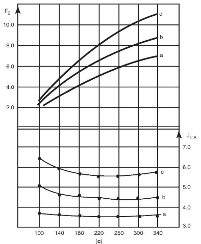
Figure 8. (Continued)
The laboratory model of this thruster was called the SPTATON. The dimensions of the device were approximately the same as those of the M-70. After optimization, this model displayed unique performance characteristics. Its efficiency (taking account of loss of xenon in the cathode compensator) approached ~ 65%, and the effective angle of divergence was < 10°. This model was built in the Moscow Institute of Radiotechnology, Electronics, and Automation (A.I. Bugrovaya’s laboratory) in collaboration with A.I. Morozov (AEI) and financial support from the SEP company of France.
The Future of SPT Designs. This design permits significant expansion of the range of working parameters. Thus, in the AEI laboratories, models using external insulators with diameters of 300 mm were tested. The power of this thruster reached 30 kW, and the thrust, depending on discharge voltage, fell in the interval of 100-150 g (1-1.5 N). The efficiency under these conditions was > 65%. The working medium was xenon. But this is far from the limit. In a quasi-stationary mode with impulses lasting ~ 10 ms, the so-called ”two-lens model” of the SPT produced hydrogen ion fluxes with energy of ~ 5 keV and an ion flux of 5 kA, that is, the accelerator power reached 25 MW, and the streaming velocity was ~1000km/s. Finally, note that SPT tests were performed using various working media, ranging from hydrogen to xenon. Performance characteristics close to the physical limit were obtained.
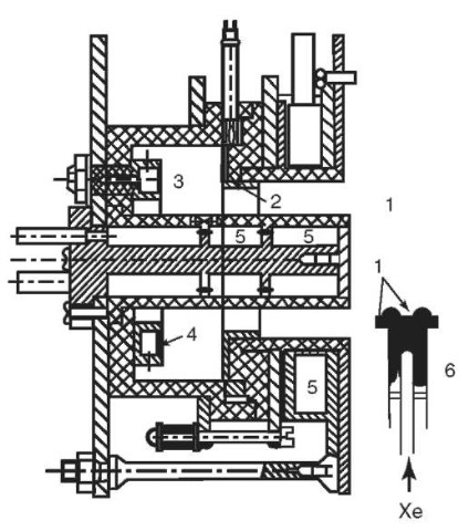
Figure 9. ATON SPT: (1) acceleration channel; (2) anode; (3) buffer volume; (4) gas distributor; (5) magnetic coil; (6) cathode.
Anode Layer Thrusters (ALT). There is a whole series of systems called ”anode layer thrusters.” However, as of the fall of 2001, only one of these has been launched into space (in October 1999), the so-called hollow-anode ALT. We will discuss this system in more detail here.
Design of the Hollow-Anode ALT. As Fig. 10 shows, this system, in many ways, looks similar to the SPT. But the length of the channel here is minimal, and its walls are not dielectric but metal at the same potential as the anode. The potential drop between the anode and the cathode (the body of the thruster) occurs within the confines of a narrow gap d < 1 mm. There are three important points to be made here. First, the ionization zone is basically concentrated inside the hollow anode. Second, the drop in potential occurs in the vicinity of the force lines, which are emitted from the gap, and third, this permits moving the acceleration zone outside the bounds of the anode cavity, if the edge of the anode strip is moved to the end of the magnetic poles and the screens covering them. This feature of the design creates the preconditions for a sharp attenuation of the ionic disintegration of the entire exhaust portion of the thruster but at the same time increases the divergence of the ion flux. As for the ionization zone, concentrated in the hollow anode, it seems that here the ionization is caused by electrons of relatively low energy. Such electrons may be generated in this hollow space because of the differential in potential, which occurs here as a result of the jump in potential near the walls of the anode. Unfortunately, local measurements of plasma parameters, including potential in the working zone of this thruster, have not been published.
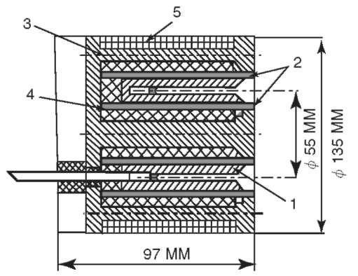
Figure 10. Schematic cross section of ALT with a hollow anode: (1) external magnetic pole; (2) anode; (3) internal screen and internal magnetic pole; (4) magnetic circuit with coils; (5) external screen.
The ALT Going into Space. The design described was implemented in a Russian-U.S. project to build and test such a thruster in space. The flight model of the thruster was developed and manufactured by the Central Scientific and Research Institute of Machine Building, where it was named D-55, the number 55 indicates the exterior diameter of the channel in millimeters. It was tested at this institute and at the Jet Propulsion Laboratory (United States).4 The external appearance of the D-55 is shown in Fig. 11.
Figure 12 shows the specific impulse and thrust efficiency as a function of power. It is evident that these characteristics are close to, although somewhat lower than the characteristics of the SPT-100 at various levels of power. Exhaustive life service tests were performed for 600 hours. Erosion of the thruster components was low, and the investigators consider that the full working life will be of the order of ~5000 hours. The remaining parts of the propulsion systems were developed and manufactured in the United States and have been flight-tested on the STEX satellite. Preliminary experiments in space were conducted on 23-24 October 1998. The thruster was turned on ten times and operated for a total of 100 minutes. A thrust of approximately 0.04 N was obtained, and orbital altitude was raised by 650 m. Although the results of long-term tests have not been published, it is known that this system implemented its assigned program during the course of a year.
ALT Evolution. The hollow-anode ALT design described was the culmination of almost 40 years of evolution. One precursor, a system for obtaining hot plasma in a trap, was developed by M.S. Joffe (Fig. 13a); ions with energy of several hundred eV were obtained by applying voltage between cold plasma coming from an arc source to the axis of a trap and the exterior body of the trap. Measurements, taken by Ye.Ye. Yusmanov, showed that here the distribution of potential was very inhomogeneous. A narrow zone with a high potential differential was observed close to the axis, whereas further away, there was an almost equipotential region.
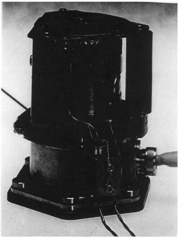
Figure 11. Exterior view of the ALT D-55 (DAL-WSF).
A theoretical model of this structure was proposed in the late 1950s by A.V. Zharinov, who was then working at the Atomic Energy Institute. He showed that the width of the layer that forms is of the order of the electron Larmor layer and confirmed this by developing a simple ”ion magnetron” (Fig. 13b) that produced a radially dispersing flux.
Soon, having transferred to the Central Scientific and Research Institute of Machine Building, he began work to use this principle to develop a plasma thruster. As in the SPT, he used a magnetic field that increased as it approached the end of the channel and obtained a stably burning discharge. This work culminated in the 1960s in creation of a two-stage ALT with a ”hollow cathode.” One problem it had was that it only operated well at high voltages, U> 2 kV, and thus, despite the use of bismuth and lead as the working media, the specific impulse was too high for current uses. The power of this thruster reached 100 kV. Its working life at 16 kW was determined by a 500-hour test.
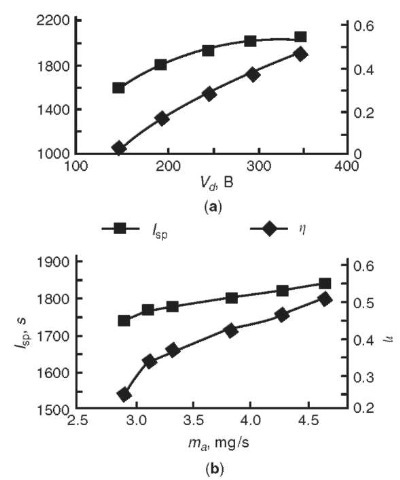
Figure 12. Efficiency coefficient and specific impulse of ALT-55 as a function of discharge voltage and consumption of xenon.
After a pause in the 1970s, spurred by the successes of SPTs, the Central Scientific and Research Institute of Machine Building began to search for an efficient one-stage model with a metal channel. Finally, in the late 1980s, A.V. Semenkin and his colleagues developed an ALT with a hollow anode, which has now flown in space.
The Future of ALT. Today, it is difficult to predict clearly the future of one-stage ALTs with hollow anodes as a universal thruster. For the time being, its performance characteristics are not as good as those of the SPT in efficiency and flow divergence, especially compared to the ATON SPT. The working life is also not clear because extrapolation is very unreliable. Nonetheless, the possibility has not been ruled out that, in the area of high specific impulses (Isp > 5000 s) and high power, thrusters in the ALT family may have great advantages. Despite these reservations it is clear that this developmental trend is worth the most serious consideration.
New Plasma Thruster Candidates
Virtually, any design for a plasma accelerator could be used for a plasma thruster, given appropriate optimization. Moreover, a number of systems, starting in the 1960s, were optimized as plasma thrusters and even tested on geophysical rockets but were never installed on a satellite for one reason or another.
(1) plasma source; (2) chamber walls; (3) plasma beam; (4) reflector (Ur — 5kW, N — 2kE, P — 5 x 10 ” 5torr). (b) A.V. Zharinov’s ion magnetron: (1) mesh end cathode;
(2) cathode; (3) cylindrical anode; (4) solid end cathode (Ur —1-10 kEV, N<1.3kE, P — 10 ” 3-10 ” 5torr).
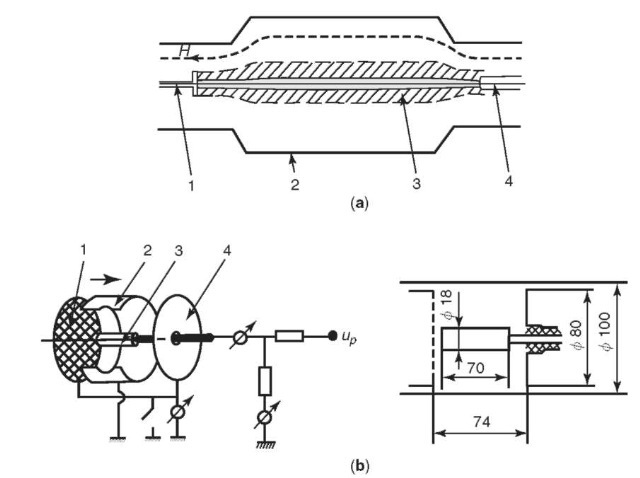
Figure 13. Ion magnetrons: (a) The set-up used by M.S. Joffe and Ye.Ye. Yushmanov:
The greatest amount of attention in the USSR (Russia) has been devoted to the so-called end accelerator—the ”high-current end accelerator” and the ”Hall end accelerator.” In the West, the latter type of plasma accelerator is called a ”magnetoplasma dynamic thruster.” We will describe both of the accelerators briefly, because for many reasons, they are not likely to become multipurpose thrusters in the foreseeable future, like the SPT, although they may prove optimal for special uses.
To facilitate understanding of the ideas underlying these thrusters, it is beneficial to remember the conditions under which they were developed. The euphoria engendered by the first successes in the conquest of space naturally gave rise to new plans. As early as 1959, there was serious discussion of sending a manned spacecraft to Mars. Evaluations showed that this would require a plasma thruster with a thrust of ~10kg — 100 N, specific impulse of ~ 10,000 s, and, thus, power of 10,000 kW at an efficiency of z — 0.5. Magnetoplasma Analog of Laval’s Nozzle. The need for thrusters on this scale naturally suggested the development of electrodynamic systems with intrinsic magnetic fields. The first thruster design of this type was proposed in 1959 in the USSR by A.I. Morozov. This was the idea of a stationary, high-current plasma thruster, representing a magnetoplasma analog of a typical gas dynamic nozzle with a central body (Fig. 14a). The central body would play the role of a cathode, and the exterior wall would serve as the anode after connection to a source of strong current.
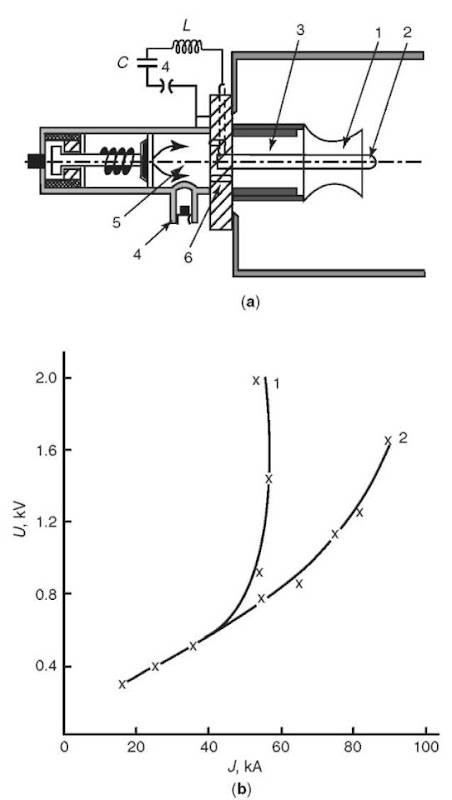
Figure 14. (a) Diagram of a model of a high-power coaxial accelerator for study in a quasi-stationary mode: (1) external electrode; (2) internal electrode; (3) buffer volume; (4) piezosensors; (5) antechamber; (6) diaphragm with openings. (b) Typical volt-ampere curve using hydrogen (1) m — 1.5 g/s; (2) m — 4.5 g/s.
Given high conductivity (or more accurately a high magnetic Reynolds number), the flow of plasma in such a system, under the influence of magnetic field pressure created by current flowing through the central electrode and the plasma itself, in elementary theory maximally approximates a gas dynamic system. But this is the case only if the current between the electrodes flows quasi-radially. Here the critical velocity, instead of the usual speed of sound (ST), is the so-called speed of fast magnetic sound:

Here p is the plasma density and CA is the so-called Alven velocity. Evaluation of the exhaust velocity yields a value ~100km/s, given reasonable fields and densities.
However, experiments in the early 1960s at the AEI with such accelerators, in a quasi-stationary mode with discharge currents of 30-100 kA, showed that current at high velocities ”does not want” to go along the radius, but starts to slip along the anode, escapes to the edge of the nozzle or even its reverse side, and induces strong erosion of the anode, rather than the cathode, as had originally been assumed. This causes the voltage to increase sharply at discharge (Fig. 14b). Formally, this may be explained by the Hall effect and visually by the dynamics of electrons in mutually perpendicular (E,V) fields. In the accelerator described, the electrons that emerge from the cathode and move toward the anode enter the perpendicular fields. That is, the azimuthal magnetic field and the electric field that (as a result of its equipotentiality) are perpendicular to the anode. As a result, if collisions are infrequent, the electrons begin to drift at velocity UE not toward the anode, but along it. The presence of a longitudinal current (slippage) along the anode leads, under the influence of Ampere’s force, to squeezing the electrons away from the anode and toward the cathode. This decreases the frequency of collisions and thus fosters an increase in the role of drift. A radical solution of the problems that arise here was found by shifting to ionic current transfer, the creation of anodes able to emit ions, but this is still very difficult.
High-Current End Accelerators HCEA. It became clear that it was necessary somehow to modify the electrodes’ geometry and operate at relatively low discharge current, until the system entered the mode ofslipping along the anode. These considerations led to the idea of ”end high-current thrusters” proposed by A.A. Porotnikov (Scientific Research Institute for Thermal Processes). The initial idea proposed cutting off the extended electrodes and leaving only the ”ends.” This is how the system got its name. But later, during the process of optimization, it became clear that the cathode really did need to be truncated, but that the anodes should be left in the shape of a relatively long nozzle.
The Design and Integral Characteristics of HCEA. An optimized HCEA design is shown in Fig. 15a. There are three main units:
1. a contoured anode
2. a cathode with many rods (wires) connected to the delivery system for the working medium
3. the insulator
The use of a multicavity cathode made of tungsten wire makes it possible to decrease the temperature of this unit significantly and at the same time, use it as a vaporizer if the working medium is delivered in its liquid phase. This was a real possibility because plans called for using light lithium.
The basic formula underlying the integral performance characteristics of the HCEA is the formula for the thrust developed by the thruster:

Here Y is a geometric factor close to 1. From this, it follows that for discharge current J = 104A, the thrust is of the order of 2 kg.
Crisis Current. The main theoretical problem the developers of the HCEA encountered was obtaining high exhaust velocities by increasing the discharge current with constant expenditure of mass. It turned out that a maximum discharge current J* exists, which is a function of design characteristics of the accelerator and loss of mass; upon approaching it, the voltage begins to increase sharply despite only small changes in the discharge current (Fig. 15b). This is accompanied by intense fluctuations, and the current begins to slip along the anode and short circuits at the edge of the nozzle or even on the back side of the nozzle This set of phenomena was named ”crisis current.” Evidently, this repeats what was observed in the coaxial accelerator described before. Entrainment of the current at the edge of the nozzle leads to the development of connections and the destruction of the nozzle even when it is made of tungsten.
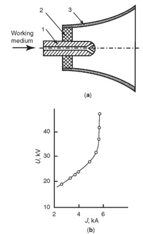
Figure 15. (a) Diagram of the high-power outlet accelerator: (1) cathode; (2) insulator; (3) anode. (b) Typical volt-ampere curve of the high-power outlet accelerator.
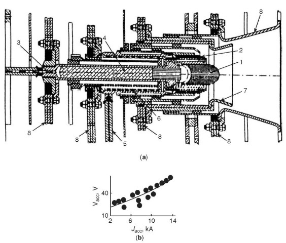
Figure 16. (a) Test stand version of the high-power two-stage HCEA: (1) central cathode; (2) peripheral cathode; (3, 5) lithium delivery pipes; (4, 6) cavities for generating weakly ionized lithium vapor; (7, 8) first and second stage anodes. (b) Typical volt-ampere curves for the two-stage HCEA.
A large number of experiments established that the critical current is a function of mass expenditure and geometry. The square of critical current proved to be proportional to mass loss. The search for a way to overcome crisis current continues. In particular, the Machine Building Central Institute has developed a two-phase HCEA, where the crisis current is either suppressed or significantly avoided. The design of this HCEA and its volt-ampere curve are shown in Fig. 16. It seems that in this model, ionic current transfer has begun to occur.
Magnetoplasma Dynamic Thrusters (MPDT). The seriousness of the crisis current and also the high level of power needed to maintain comparatively high performance parameters of the HCEA have naturally stimulated a search for modifications that would give rise to high performance at significantly lower power.
It was possible to take the first step by using a simple technique, placing a magnetic field coil on the HCEA (Fig. 17). It should be noted that, independently of work in the USSR, a similar design was proposed and studied in the United States and then in Germany and Japan.
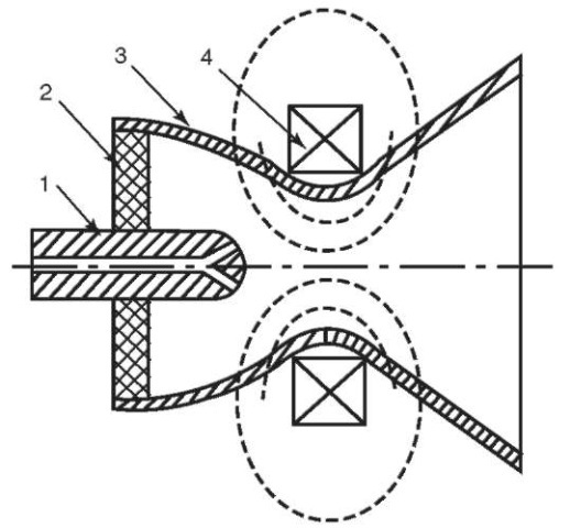
Figure 17. Diagram of the magnetoplasma dynamic thruster: (1) cathode; (2) dielectric; (3) anode; (4) magnetic field coil.
As a result, a unique hybrid of the SPT and HCEA was developed. This accelerator actually did increase the performance characteristics in the area of lower power (~ several tens of kW) compared to the HCEA but did not bring them to the level of the SPT, in spite of the fact that these accelerators were the object of virtually continuous work (although of varying intensity), starting in the early 1950s and continuing to the present.
The physical process in the MPDT proved to be rather complex. Its performance characteristics are sensitive to the magnitude of the discharge current, as well as to the magnitude of the magnetic field and system geometry. For an approximate evaluation of thrust, we may use the formula,

where BA and BK are the induction of the external magnetic field at the ends of the anode and cathode and DA is the diameter of the anode. The characteristic value is ~ 0.3-0.4.
It proved to be that the MPDT was also subject to the effect of crisis current and the high performance characteristics could be obtained only with lithium at relatively high discharge power. Thus, at the Moscow Aviation Insti-

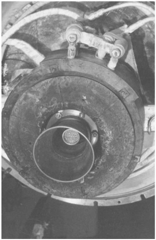
Figure 18. Photograph of a MPDT with power of up to 200 kW. The anode diameter at the end is 160 mm.
