Introduction
Having only begun in the early 1960s, planetary-exploration spacecraft design is a fairly new art (1). Between 1962 and 1973, NASA designed, built, and launched 10 spacecraft named Mariner to explore Venus, Mars, and Mercury for the first time. In 1962, the Jet Propulsion Laboratory (JPL) launched the Mariner 2 spacecraft (Fig. 1) to explore Venus (2). In 1965, Mariner 4 flew by Mars and captured the first close-up photos of another planet.
Each year since 1962, NASA, the USSR, Japan, or the European Space Agency has launched at least one planetary-exploration spacecraft (3). Two of the best known are NASA’s Voyagers (4-6) (Fig. 2), which were launched in 1977, two years after NASA’s Viking mission (7) sent landers and orbiters to Mars (Fig. 3). Today, 24 years after launch, Voyager 2 has completed a tour of Jupiter, Saturn, Uranus, and Neptune, and still returns data from a distance of 64 AU (astronomical units, the average Earth-Sun distance; one AU is 150 million kilometers), which takes nearly nine hours of light time. NASA spacecraft have visited every planet in the solar system except Pluto, and orbited Venus, Mars, and Jupiter. In 1975, the USSR’s Venera 9 and 10 spacecraft sent the first photos from the surface of another planet (Venus); in 1986, the European Space Agency’s Giotto spacecraft captured the first detailed photos of a comet’s nucleus (Halley’s). The NASA/JPL Cassini spacecraft is due to enter Saturn orbit in 2004 (8). The NASA/APL MESSENGER spacecraft is due to orbit Mercury in 2009 (9). MESSENGER is being built by the Johns Hopkins Applied Physics Laboratory (APL),which also built the Near Earth Asteroid Rendezvous 10 (NEAR) spacecraft (Fig. 4) that orbited and touched down on the asteroid Eros in February 2001.
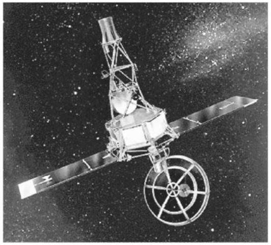
Figure 1. Mariner 2, launched in 1962, became the first spacecraft to fly by another planet, studying the Venusian atmosphere and surface. During its 32-month journey to Earth’s neighbor, the craft made the first-ever measurements of the solar wind, a constant stream of charged particles flowing outward from the Sun. It also measured interplanetary dust, which turned out to be scarcer than predicted. In addition, Mariner 2 detected high-energy charged particles coming from the Sun, including several solar flares, as well as cosmic rays from outside the solar system. As it flew by Venus on 14 December 1962, Mariner 2 scanned the planet with infrared and microwave radiometers, revealing that Venus has cool clouds and an extremely hot surface. Mariner 2′s signal was tracked until 3 January 1963. The spacecraft remains in orbit around the Sun.
This article addresses the important elements of planetary-exploration spacecraft (PES) design. The scope of this article includes those spacecraft that fly by, orbit, or land on other planets, asteroids, or comets. Planetary-exploration spacecraft are truly fascinating machines, and their missions are some of humankind’s most audacious endeavors. Spacecraft elements are described in some detail, and the principal focus is on the system design and the technical subsystems. Ground stations, launch vehicles, science, and navigational elements (11) are not addressed.
Requirements and Constraints on Planetary-Exploration Spacecraft Design
Introduction. PES design is a process that is driven by the unique nature of planetary-exploration missions and their scientific investigations. Mission and science requirements are used to determine spacecraft system-level requirements, and in turn subsystem requirements, as shown in Fig. 5. Basically, where the mission goes, how it gets there, and what it does drives the spacecraft design.
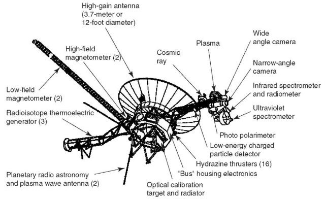
Figure 2. The twin spacecraft Voyager 1 and 2 flew by and observed Jupiter and Saturn; Voyager 2 went on to visit Uranus and Neptune. In 1998, Voyager 1 became the most distant human-made object in space.

Figure 3. The Viking Mars Lander spacecraft is shown here. Viking 1 landed on Mars on 20 July 1976, and Viking 2 landed on 3 September 1976. Viking 1 was the first successful soft landing of a spacecraft on Mars. The two Viking spacecraft were identical, and they sent back photographs of the Martian surface. They also collected a wealth of data on atmospheric composition, meteorological conditions, soil samples, and seismic activity. Each Viking spacecraft also carried a set of experiments that looked for biological activity on the surface of Mars. The results were negative. Viking 1 transmitted data for more than six years. Viking 2 was shut down on 11 April 1980.
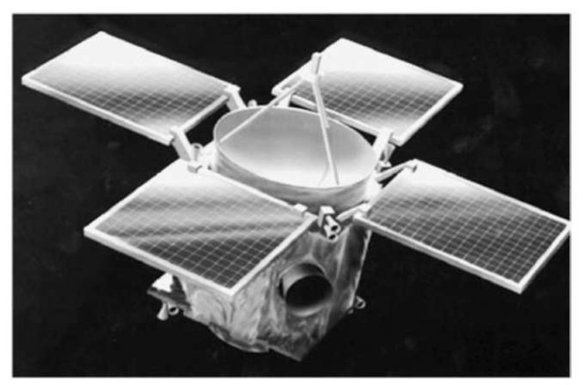
Figure 4. In 1996, NEAR-Shoemaker was the first Discovery Program spacecraft to be launched, and five years later, in February 2001, it became the first ever to orbit and land on an asteroid. Using six highly specialized instruments to gather data about its primary target, asteroid 433 Eros, NEAR has answered many fundamental questions about the nature and origin of asteroids and comets. The spacecraft snapped 69 detailed pictures during the final 3 miles (5 km) of its descent, the highest resolution images ever of an asteroid that showed features as small as one centimeter across.
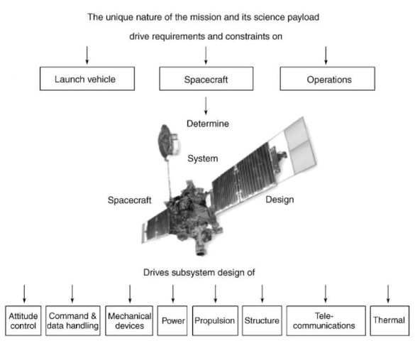
Figure 5. Planetary spacecraft design flow
The remainder of this section presents a brief discussion of important mission and system requirements and constraints that drive the design of a planetary-exploration spacecraft.
Mission Objective. The mission objective is to perform scientific exploration and investigation. To conduct the desired scientific investigation, it is necessary to transport the scientific payload to the destination and provide power, environmental protection, the proper instructions and orientation for performing measurements and the necessary communications technology for transmitting the resulting data to Earth. A large complex of people, computers, communication lines, and tracking antennae on Earth is needed to guide and support the mission. Very High Standards. Two paramount constraints for all missions are that, once launched from Earth, spacecraft hardware can never be repaired, and there is very low tolerance for any failure. Because overwhelming media coverage ensures that the world will instantly learn of any problem, no space agency that commits public resources to build, launch, and operate a PES welcomes even the perception of failure. All of this creates enormous pressure on a PES and its mission to succeed. Consequently, the spacecraft must be designed, built, and operated to extraordinarily high standards.
Instruments. The fundamental function of a PES, (what it does) is to transport the instruments needed to perform the scientific and exploratory investigations. Most of these instruments are passive devices that operate in parts of the electromagnetic spectrum, including long-wavelength radio waves, the infrared (IR), visible, the ultraviolet, X rays, and gamma rays. Some instruments, such as radar and light detection and ranging (LIDAR), are active-sensing. The instruments place requirements on the spacecraft, such as mass, power, pointing, data rate, and data volume. Some instruments place special requirements on the PES. Spacecraft that carry sensitive magnetometers must be ”magnetically clean”; that is, designs must specify special electronic parts, shielded components, and sometimes equipment to generate and maintain offsetting magnetic fields. To avoid receiving its own spacecraft emissions, for example, a magnetometer may need to be flown at the end of a long boom; this greatly affects the attitude control-system design. A gamma-ray detector onboard means that overall spacecraft emissions must be checked and components altered or removed so that their output does not swamp the target planet’s signals. Planetary Protection. Planetary protection is a unique requirement for planetary spacecraft. It means protecting another planet’s environment from Earth’s biological contamination and protecting Earth’s environment from extraterrestrial contamination. Usually applied to landers, it is critically important for those missions whose objective is to return a sample of another planet to Earth; it also applies to orbiters whose orbit may someday degrade, causing the spacecraft to hit the surface. To illustrate, consider the Mars orbiter that NASA currently plans to launch in 2005. The planetary protection requirements for this mission are that
• all flight hardware is to be assembled and maintained in class 100,000 clean rooms (or better);
• the probability of an impact on Mars by any part of the launch vehicle (including the upper stage) that leaves the vicinity of Earth must not exceed 10 – 4; and
• the probability of an impact on Mars by the orbiter due to all causes must not exceed 0.01 for the first 20 years after launch and 0.05 for the succeeding 30-year period. To meet part of the third requirement, the flight system must be designed with a reliability for the mission (launch through the attainment of the final orbit) better than 0.99, and the spacecraft-ballistic coefficient must be considered.
Solar System. The most important influence on the design of a planetary-exploration spacecraft is the solar system itself. A spacecraft designed to travel the solar system must successfully operate in the solid-particle and radiative environments of the solar system. The spacecraft must operate far from Earth and at a Sun range greatly different from 1 AU. The large Earth range implies a significant light time for signals sent to and from the spacecraft, long trip times to the final destination, and the need for precise navigation. Launch dates for PES are inflexible, may occur only once every 2 years (or less frequently), and are set by the well-known, but totally inflexible motion of the planets around the Sun.
Rigid and Infrequent Launch Windows. Solar system dynamics are well known, totally fixed, and make for rigid, inflexible, and infrequent launch windows separated by many years—even decades. There is enormous pressure to deliver interplanetary missions to the launch pad on time because missing a window results in intolerable consequences for missions and careers alike. For Mars, for example, a mission may have to wait two years for the next opportunity. Missions to the outer planets may wait much longer. The alignment of the planets Jupiter, Saturn, Uranus and Neptune that the Voyager 2 spacecraft used for minimum trip time occurs about once every 175 years. In contrast, if an Earth-orbiting spacecraft arrives late for a launch window, another one will open in the following week or month. Compared to a typical Earth orbiter, a planetary spacecraft’s launch opportunities are very infrequent, and the consequences of failure are especially severe. This consequence of failure creates a greater need for high reliability that is usually implemented through greater robustness in design (parts quality, fault protection, and use of redundancy).
Round-Trip Light Time. An important spacecraft-design constraint is round-trip light time—the minutes or hours that it takes for a distant spacecraft’s signal to reach Earth, plus the control-signal return time. Because of the solar system’s vast expanse, a typical Earth-to-PES distance is usually many orders of magnitude greater than the Earth-to-Earth-orbiter distance. A PES at 1 AU from Earth, for example, is 4200 times farther away than a geosynchronous Earth orbiter (GEO), which receives a ground signal from Earth in only a tenth of a second. A spacecraft at Mars may be as much as 2.5 AU from Earth—a oneway, light-travel time of 20 minutes. At Saturn, Cassini’s maximum distance to Earth requires a one-way, light-travel time of more than 1.5 hours. Despite PES radio signals traveling at the speed of light, the spacecraft designer must consider the long time signals take between spacecraft and Earth.
To minimize mission risk so that it is similar to that of an Earth orbiter, distant spacecraft must operate more autonomously, especially regarding fault detection and recovery. Long round-trip light time affects the way planetary spacecraft are commanded. An Earth orbiter can wait for a command signal before it transmits its recorded telemetry; a planetary spacecraft cannot.
Spacecraft that perform split-second events, such as landing on Mars, cannot afford to wait for a command to be acknowledged before another is sent. For example, if a spacecraft transmits a distress signal, while executing split-second events, such as entering Mars’ atmosphere, Earth would receive it only after the probe is on Mars’ surface—too late for ground controllers to help.
Earth Range. A spacecraft’s telecommunications subsystem is especially driven by a planetary explorer’s large Earth range (distance to Earth). The strength of the received signal is inversely proportional to the square of the range. The power per unit area received from a GEO spacecraft is 4200 squared or 72 dB larger than that from the planetary spacecraft at a range of 1 AU from Earth. To receive low-strength signals, NASA built special ground stations collectively called the Deep Space Network (DSN) (12) (Fig. 6). The DSN is an international asset that tracks planetary spacecraft from many countries, and the DSN receiving network has special interface requirements for planetary spacecraft. Because navigating interplanetary space requires extremely accurate clocks, the DSN uses a hydrogen-maser-based frequency reference whose accuracy is equal to the gain or loss of 1 second in 30 million years. The maser is a reference that generates an extremely stable uplink frequency that the spacecraft uses, in turn, to generate its coherent downlink.
Even using the DSN, a planetary probe’s uplink and downlink data rates are lower than those of an Earth orbiter. If a planetary spacecraft is turning very quickly because of a mission need or tumbling because of a fault, low uplink rates can preclude commanding. Because of the high signal strength, an Earth orbiter can receive a command in nearly any attitude, but distant planetary probes must be in specific attitudes or they will not receive the signal. A limited downlink rate can strongly drive data storage, data compression, and optimal recording of data. A limited downlink rate may also mean that a spacecraft can transmit only a small part of the data that its instruments can produce.
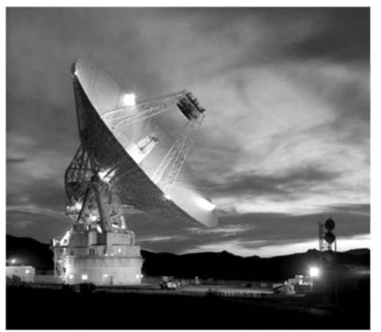
Figure 6. The Deep Space Network (DSN) is an international network of antennae that supports interplanetary spacecraft missions and radio and radar astronomy observations that explore the solar system and the Universe. Via its vital, two-way communications link, the network guides and controls interplanetary explorers and brings back the images and new scientific data that they collect. All DSN antennae are steerable, high-gain, parabolic-reflector antennae.
Mission Energy and Trip Time. The destinations for planetary spacecraft are energetically a ”long way from Earth.” The mission energy manifests itself not only in the required change in spacecraft velocity (known as AV) for departure from Earth and after launch but also in trip time to the destination. Because the required mission energies are so large, most planetary mission trajectories are ”minimum energy” trajectories (13). A consequence of these ”minimum energy” trajectories and the vast distances are long trip times to the destination. The largest AV for Earth-orbiting spacecraft is normally required by a geosynchronous communication spacecraft where the AV required to go from low Earth orbit (LEO) to GEO is about 4200 m/s. The total AV beyond LEO for some typical planetary missions are as follows. For a low, circular Mercury orbiter where the trip time is about 4 years, the required AV is 7000 m/s. A direct 0.4-year trip to a low Venus orbit requires about 6900 m/s. For a Pluto orbiter that has a 20-year trip time, 15,000 m/s is required. Usually, the launch vehicle for both Earth orbiters and planetary spacecraft supplies part of this AV. Several of these planetary missions have not been performed because the combination of AV and trip time is so large.
Because of the large AV for many planetary missions, methods besides traditional chemical propulsion have been developed, such as electric propulsion systems and the use of the target-body atmosphere to aid in capture at the planet. Aerobraking (14,15), as this is known, is a technique wherein the spacecraft is deliberately flown into the top of the target planet’s atmosphere. There, the drag on the spacecraft acts like a brake, and spacecraft energy is dissipated. Aerobraking uses almost no propellant to provide AV to change the kinetic energy of the spacecraft. The NASA/JPL Mars Global Surveyor (16) spacecraft (Fig. 7) and also the Mars Odyssey (17) spacecraft (Fig. 8) that arrived at Mars in 2001 used aerobraking.
Long trip times and minimum-energy trajectories require that planetary spacecraft be extraordinarily reliable. Some Earth orbiters may live as long as 15 years, but their operations in orbit begin only a few weeks after launch. For many planetary spacecraft, their missions do not begin until they reach their targets, which could take years. For example, Voyager 2 traveled 12 years before it successfully encountered Neptune. The Cassini probe must travel for 6.6 years before its Saturn orbital operations begin. So, it is many years after launch that these spacecraft maneuver for orbit insertion and open into their final mechanical configuration. The ship’s mechanisms, components, and instruments must remain workable during those years traveling through space and when activated, must perform perfectly.
Extended missions also affect spacecraft operations. For example, when cruise time is lengthy, additional operational modes, software, and procedures are needed. Because of personnel turnover during missions measured in decades, retraining is also absolutely critical if fatal errors are to be avoided in the mission’s end game, when the people who designed the final procedures have moved on. To reduce peak-year costs for multiyear-missions, command sequences for planetary encounters are not developed until after launch. Therefore, spacecraft design must accommodate new flight software that will be tested ”on the fly.” Changes in data-system technology also affect lengthy missions, and vice versa. Ground-system components, for example, may be upgraded during the mission. On the positive side, for long-cruise-time missions, there is time to diagnose and hopefully correct any errors before the primary mission begins. Space Radiation Environments. Because the planetary-spacecraft environment is very different from that of an Earth orbiter, it also impacts the system. Although usually stable, this distant environment is uncertain; one of the mission goals may be to learn more about it. To keep the risk level close to that of an Earth orbiter, a distant mission may require more environmental analysis and margin. PES design must accommodate space radiation and solid particles. The three types of space-radiation environments are planetary-trapped radiation, galactic cosmic radiation, and solar-energetic particles.

Figure 7. The Mars Global Surveyor (MGS) entered Mars’ orbit in late 1997 and was the first successful mission to the red planet in two decades. MGS scientific instruments include a high-resolution camera, a thermal-emission spectrometer, a laser altimeter, a magnetometer/electron reflectometer, an ultrastable oscillator, and a radio-relay system. Beginning its prime mapping mission in early 1999, MGS studied the entire Martian surface, atmosphere, and interior from a low-altitude, nearly polar orbit during one Martian year (almost two Earth years). Having completed its primary mission in early 2001, it continues in an extended mission phase. MGS has returned more data about the red planet than all other Mars missions combined.
Because the trip through them is short, spacecraft are not affected by Earth’s radiation belts, but other planetary belts can be a serious threat. Even short gravity-assist passages through Jupiter’s system, for example, will expose the spacecraft to most of a mission’s total radiation dose. Heavy-ion fluxes will also disrupt critical mission functions that have single-event effects (SEE).
Galactic cosmic radiation (GCR) is composed of high-energy nuclei. Earth’s magnetic field provides some shielding against this radiation for spacecraft in low-to-medium Earth orbits. Even so, the radiation flux from GCR in interplanetary space is low and does not contribute significantly to the mission’s total ionizing dose, but sufficient heavy ions are present in the GCR populations to create a SEE threat to some electronic parts throughout the mission.
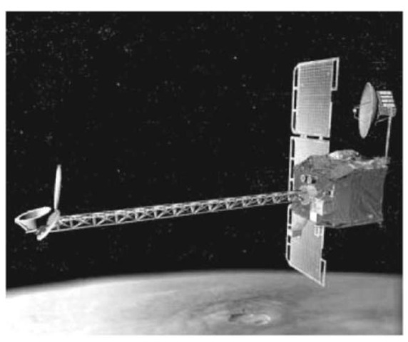
Figure 8. Mars Odyssey has a mass of 758 kg and carries scientific instruments, including a thermal emission imaging system, a gamma-ray spectrometer, and a Mars radiative environment experiment. It arrived at Mars in late 2001. The Odyssey orbiter’s mission is to determine the planet’s surface composition; detect water and shallow, buried ice; and to study the radiation environment. In May, 2002 Odyssey scientists announced that their instruments had detected enormous quantities of water ice just below Mars surface. It has long been thought that Mars’ surface consists of rock, soil, and icy material, but the exact composition is largely unknown. Odyssey will help identify soil minerals and surface rocks, and it will study small-scale geologic processes, as well as future landing-site characteristics. By measuring the amount of hydrogen in the entire planet’s upper meter of soil, the spacecraft will uncover the amount of water available for future exploration and also more clues about Mars’ climatic history. The orbiter will also collect radiation data to help assess risks to future human explorers, and it will act as a communications relay for future Mars Landers.
Solar-energetic particles are also attenuated by Earth’s magnetic field, but in interplanetary space, fluxes due to a given solar event may be two to three times more intense than near Earth and thus present both a total dose and SEE threat. When they are outside Earth orbit, solar-event fluences dissipate in inverse proportion to the square of the heliocentric distance. So, outer planet missions are reasonably safe. But inside 1AU, it is a different story. The hazards of solar-event radiation can be considerable for missions that visit Venus or Mercury. For instance, even a moderate solar event can incapacitate a spacecraft that passes close to the Sun.
The solid-particle danger to interplanetary spacecraft has two origins: mi-crometeroids (particles that orbit the Sun) and dust (particles that orbit other solar-system bodies). Artificial debris is encountered only in a mission’s immediate post launch phase. Although there are few particles in interplanetary space, encounter velocities are high (~ 15-50 km/s) and can be very damaging. The nature of the encounter dictates the velocity. Because Cassini will go into a
Saturn orbit, its encounter velocity with the planet’s ring particles is much lower than Voyager’s speed when it passed close to Saturn to obtain a gravity assist. Sun Range. The Sun range (distance to the Sun) especially affects PES power and thermal-control subsystems. Widely varying spacecraft-Sun distances—especially when they change during a mission—dramatically impact the design. For example, Cassini flew by Venus (0.6 AU) for gravity assists and headed out to Saturn (10 AU) to conduct its prime mission. A Mercury orbiter (18) encounters a huge thermal range: its illuminated side receives 10.6 suns (mainly short-wave IR), and the other side sees 8.5 suns (long-wave IR reflected from the planet’s surface). And a few hours later in solar eclipse, the orbiter will see no ”suns” on either side.
Sun-range effects on the power subsystem are directly opposite, depending on whether the mission destination is less than or greater than 1 AU. Spacecraft going to the inner planets have the problem that their power output increases with mission time, up to a point where solar cells developed for Earth orbiters are no longer usable without special coatings, or they are not usable at all. The spacecraft may solve its excess-heat problem by pointing away from the Sun or by shunting the excess power and radiating the excess as heat.
The opposite problem is true for a spacecraft bound for an outer planet, because its solar-array power gradually drops off and finally stops. Special solar arrays designed for low-light, low-temperature conditions are required. In some cases, a PES will use a radioisotope thermoelectric generator (RTG) for electric power production. Another problem for outbound spacecraft is that unless ”makeup heat” is provided or heat is conserved, components may cool below safe operating temperatures. Experience dictates that outer-planet missions must invest more of their development time and money in power-efficient technologies. Navigation (11). Because of the size of the solar system and the motions of the planets, a planetary-exploration spacecraft must be carefully navigated to its destination. Radiometric data can be used to determine spacecraft position relative to a planet—to within a few kilometers at best. Velocity data are accurate to within a few tenths of a mm/s. Nongravitational acceleration caused by unplanned or unmodeled spacecraft accelerations such as outgassing, leakage, or uncoupled attitude-control maneuvers can greatly affect spacecraft navigation. Acceleration due to these forces must be kept within a few mm/s2, accurately modeled, and reported. In 1999, perhaps because of an error in modeling these forces, engineers believe that the Mars Climate Orbiter (19) entered the Mars atmosphere too low to achieve orbit and probably burned up.
Planetary-Exploration Spacecraft Subsystem Design
Subsystems are individually tailored and integrated to implement the overall system design (20). Subsystems include structure, thermal, mechanical devices, command and data handling, attitude control, telecommunications, power and propulsion. Table 1 presents the subsystem characteristics of several planetary-exploration spacecraft.
Structure. The structural subsystem includes primary and secondary mechanical and structural members that support and align all spacecraft flightsubsystems and equipment during ground handling, launch, and flight. Structure also protects against natural and induced environments such as vibration, meteoroids, radiation, and electromagnetic interference. Generally, the structure subsystem of an Earth-orbiting and a planetary spacecraft are alike. Thermal. The thermal subsystem heats or cools spacecraft components to maintain them within operating (and nonoperating) temperature ranges. This function includes meeting special temperature requirements of components such as batteries and cryogenic instruments. Temperature control must be effective throughout the mission’s prelaunch, launch, cruise, and operational phases.
Table 1. System Characteristics of some NASA Spacecraft
Stated simply, this is a planetary spacecraft’s thermal-design strategy: Use passive components whenever possible because they use less power, operate more simply, and are thus more reliable than active ones. The idea is to minimize temperature sensitivity due to external and internal heat fluctuations and emphasize passive techniques (for example, blankets, radiators, coatings) over active ones (for example, heat pipes, fluid loops, thermostatically controlled heaters).
Earth orbiters have ”in Sun” and ”in eclipse” design points, whereas planetary orbiters have ”in Sun” and ”in eclipse” conditions that may vary dramatically during the mission because of the change in Sun range. To design the thermal subsystem confidently for a planetary mission, additional thermal analyses and testing are required. In addition, for those missions going closer than 1 AU to the Sun, available thermal-control materials and paints may be limited, and entirely new ones may need to be developed. A requirement to keep large amounts of propellant at a given temperature during a long cruise between launch and orbit insertion may be the main power and thermal design driver.
All spacecraft use multilayer blankets for thermal control. For PES, the multilayer thermal-insulation blankets also provide some protection against mi-crometeoroid impacts. They are made of Kapton, Kevlar, or other fabrics strong enough to absorb energy from high-velocity micrometeoroids before they damage spacecraft components. Impact hazards are greatest when crossing the ring planes of the Jovian planets. Voyager recorded thousands of hits in these regions, fortunately from particles no larger than smoke particles. Spacecraft, sent to comets such as Stardust, (21), carry massive shields to protect them from hits by larger particles.
Mechanical Devices. Mechanical devices perform functions such as separating a spacecraft from its launch vehicle, deploying booms, articulating high-gain antennae and solar arrays, jettisoning aeroshells and deploying parachutes, releasing instrument covers, and controlling fluid flow in propulsion and pressur-ization systems. These devices must operate at 100% reliability for many years after launch. Earth orbiters achieve their final spacecraft mechanical configuration early in their lifetime. But, because cruise time to a mission site is very long, it may be many months or years before a PES assumes its final mission configuration. The final deployment of the Mars Observer spacecraft’s (22) solar panels, high-gain-antenna boom, and a science-instrument boom were to have occurred after insertion at Mars, nearly 1 year after launch.
The Cassini (23) spacecraft will release a large Titan atmospheric probe 7 years after launch. There is always concern that mechanical-actuation devices may be less reliable after a long time in space. Because these devices are candidates for single-point failures, a design remedy is to add redundant actuators.
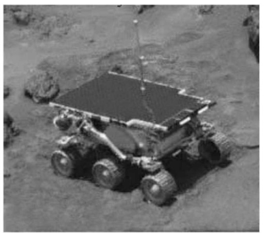
Figure 9. The Mars Pathfinder’s Sojourner rover is 280 mm high, 630 mm long, and 480 mm wide. Using rover and lander images, an Earth-based operator controlled the rover. But, because of the light-time delay of 10-15 minutes, an onboard, hazard-avoidance system allowed it some autonomous control as it explored the surface, so it would not always have to wait for commands from Earth. On the rover, 0.2 square meters of solar cells, provide energy for several hours of operations per sol (1 Martian day — 24.6 Earth hours).
Mars Pathfinder, which successfully deployed Sojourner rover (Fig. 9) on Mars, depended on 42 pyrotechnic events during its successful atmospheric entry, descent, and landing. Design practices emphasize large strength or force margins, redundancy where practical (for example, bearings within bearings), vacuum-compatible materials and lubricants, and special attention to the effects of thermal expansion and contraction. All mechanical devices are extensively tested to verify margins and lifetime, and intentional ”fouling” tests are conducted to achieve extra confidence. A mechanical actuation system that successfully operated on an Earth orbiter may fail to work on a planetary spacecraft. An example is the Galileo (Fig. 10) spacecraft’s high-gain antenna that failed to open completely. Though the actual cause will never be known, extensive prelaunch handling—rather than the long-storage time en route to Jupiter—may have been the culprit.
Command and Data Handling. The brain and memory of a spacecraft are the command and data-handling subsystem (C&DH). Consisting mainly of computers, memory, and input/output devices, it also provides the spacecraft’s time reference. The C&DH also performs real-time and preprogrammed functions such as decoding ground commands; distributing discrete and coded commands to subsystems; responding to onboard-generated events; and collecting, managing, and storing scientific and engineering data. Primary design considerations include processor speed, quantity, and access speed of memory, as well as fault-detection-and-correction techniques. In some cases, onboard processing of optical-navigation images may be required to reduce the quantity of data transmitted to Earth or to reduce response time for critical events. The need for autonomous fault-diagnosis and recovery on planetary spacecraft requires that designers develop, design, and validate additional onboard software. And in turn, fault-protection software needs computer memory, processing power, and additional telemetry data.
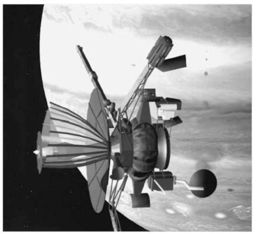
Figure 10. The Galileo spacecraft arrived at Jupiter in late 1995, entered orbit, and dropped its instrumented probe into the giant planet’s atmosphere. Since then, it has made dozens of orbits around Jupiter and flown close to each of its four major moons. Galileo discovered that the cratered surface of Jupiter’s moon, Europa, is mostly water ice, and there is strong evidence that it may cover an ocean of water or slushy ice. Galileo also found indications that two other moons, Ganymede and Callisto, have layers of liquid saltwater as well. Half of the spacecraft contains pointable instruments, such as cameras, and is held fixed in relation to space; the other half, containing instruments that measure magnetic fields and charged particles, slowly rotates to optimize the measurements. Other major scientific results include details of varied and extensive volcanic processes on the moon Io, measurements of conditions within Jupiter’s atmosphere, and the discovery of a magnetic field generated by Ganymede. Despite heavy radiation doses, Galileo continues to return scientific data in an extended mission phase.
Compared with an Earth orbiter, a planetary spacecraft must have additional intelligence and autonomy to monitor and control itself. The PES is always a great distance from home, is tracked as little as once per day or week, and cannot communicate with Earth during certain periods. For example, during superior conjunctions (when the spacecraft and Earth are on opposite sides of the Sun), autonomous fault-protection software must intervene in case of an onboard failure. Light time and tightly constrained tracking schedules prohibit ground teams, who control and monitor the spacecraft, from immediately responding to onboard anomalies. When failures occur, C&DH fault-protection algorithms must detect them and in the case of a communications interrupt, reestablish contact with Earth. A spacecraft may have many different fault-protection monitoring algorithms running simultaneously and must be prepared to request C&DH to take action. The command-loss timer, for example, is reset to a predetermined value, for example 1 week, each time a command arrives from Earth. If the timer runs down to zero, it is assumed that the receiver or another component in the command string suffered a failure. The fault-protection response may then be to switch to redundant hardware to reestablish radio contact with Earth.
Other fault-protection responses include requesting safe mode; shutting down or reconfiguring components to prevent damage; or performing an automated, methodical search to re-establish Earth-pointing to regain communications. Though entering safe mode may temporarily disrupt scientific data gathering, it provides reliable spacecraft and mission protection. Read-only memory (ROM) usually carries a minimal set of safe-mode instructions (the Magellan spacecraft (Fig. 11) ROM contained only 1 kB of this code); commands can hide in ROM for the worst imaginable scenarios of runaway-program executions or power outage. More intricate safe-mode and fault-protection routines (for example, ”contingency modes”) and parameters for use by the ROM code typically reside in random access memory (RAM), where they can be updated as needed during the mission lifetime.
Attitude Control. The attitude control subsystem keeps spacecraft motions stable and precisely points and orients the spacecraft (or single instruments) despite gravity gradients, propulsion-system torque, solar pressure, and sometimes micrometeoroid impacts. Precise pointing is important because the high-gain antenna has to acquire Earth contact; scientific instruments must collect data; thermal radiators have to be properly positioned; Sun-and-star sensors must provide attitude references; and to generate maximum power, solar panels have to be Sun-oriented. The spacecraft must also point in the correct direction to make precise trajectory-control maneuvers.
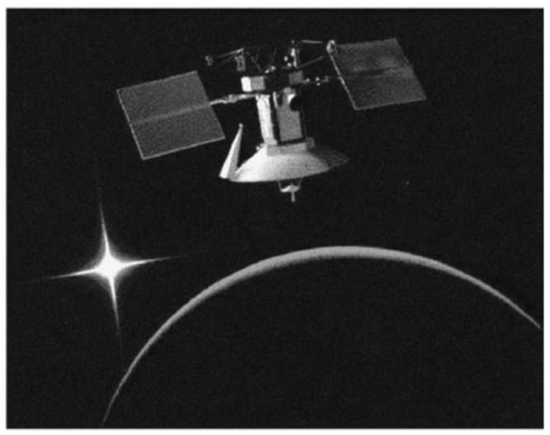
Figure 11. The Magellan spacecraft was carried into Earth orbit by the Space Shuttle Atlantis and was propelled to Venus by a solid-fuel motor. Entering orbit in late 1990, Magellan pierced Venus’ veil of swirling clouds, mapped its surface with its imaging radar, and dramatically improved upon the mapping resolution of orbiters that the United States and the Union of Soviet Social of Republics sent in the 1970s and early 1980s. Flight controllers tested a new maneuvering technique called aerobraking that uses a planet’s atmosphere to slow a spacecraft. At mission end in 1994, Magellan’s orbit was lowered a final time, and it plunged to the planet’s surface; contact was lost the following day.
Because large amounts of propellant can be expended, the attitude-control subsystem design must take into account the resulting dramatic changes in a spacecraft’s inertial properties as a function of mission time. A PES is not orbiting Earth, so the attitude-control subsystem must operate differently. Spacecraft orbiting other planets sometimes use horizon sensors, so Earth-horizon sensors must be adapted to a different atmosphere or no atmosphere. GPS receivers cannot be used for orbit or attitude information. Without Earth as an attitude reference, planetary spacecraft become highly dependent on celestial sensors and celestial-attitude determination. Without a well-characterized, adequately strong magnetic field, magnetic-torque rods cannot be used for attitude maneuvers or to desaturate reaction wheels. Planetary spacecraft may be sent to orbit planets that have magnetic fields (Jupiter), but usually the magnetic field is not well enough known to be used for attitude determination and control.
Because of the various forces acting on it, an unstabilized spacecraft will acquire rotational motion and tumble chaotically. Like Earth-orbiting spacecraft, a PES may be spin-stabilized or three-axis controlled. Spinners that are relatively inexpensive have been used in precursor missions to the outer solar system. Pioneers 10 and 11 (Fig. 12) were intended to explore the environments of Jupiter and Saturn through which the more sophisticated Voyager spacecraft would have to pass. For spinners, the gyroscopic action of the rotating spacecraft mass is the stabilizing mechanism. Propulsion-system thrusters are fired only occasionally to make desired changes in the spin-stabilized attitude.
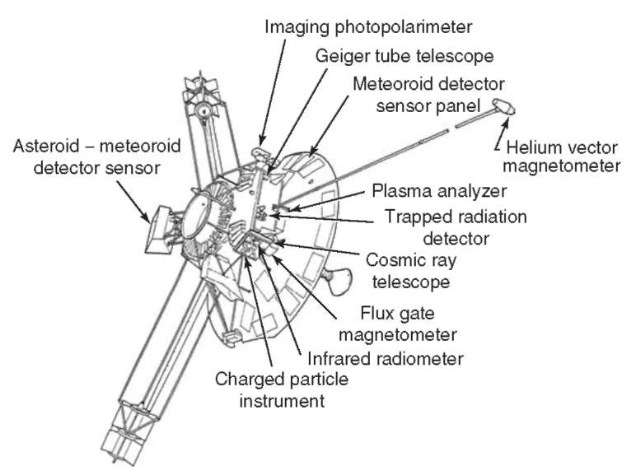
Figure 12. Pioneer 10 and 11 spacecraft: Pioneer 10 was launched in 1972 and flew past Jupiter in 1973. The spacecraft measured the radiative field, the magnetic field, and other elements of the environment to prepare the way for the Voyager spacecraft that was launched in 1977 (see Fig. 2). Pioneer 10 was the first spacecraft to fly past the asteroid belt, to fly past Jupiter, and the first-human-made object to leave the solar system as defined in extent by the orbit of Pluto in 1983. Pioneer 11 was launched in 1973 and was the first spacecraft to fly past both Jupiter and Saturn. In 1979, Pioneer 11 passed between Saturn and the ring plane just outside the A-ring and its visible ring to ensure that Voyager 2 could make a thorough investigation of the Saturn system during its flyby in 1981.
Spinners have also been used to launch probes into planetary atmospheres. In this case, the mother ship imparts the proper attitude and spin rates. Examples of this are the Pioneer Venus Multiprobe Spacecraft (Fig. 13) and the Galileo Probe (24) into the atmosphere of Jupiter (Fig. 10). Finally, spinners can be used effectively for radar-altimetry mapping missions such as the Pioneer Venus Orbiter (1978) and the recently completed Lunar Prospector Mission (Fig. 14).
Alternatively, a spacecraft may be designed for active three-axis stabilization. One method is to use small propulsion-system thrusters to nudge the spacecraft back and forth continuously within a dead band of allowed attitude error. Voyagers 1 and 2 have been doing this since 1977 and have consumed about 70 kg of their 106 kg of propellant as of April 2001. They are using propellant at the rate of about 7 grams per week (6). Another method is to use electrically powered reaction wheels, as on Mars Global Surveyor and the recently launched Mars Odyssey. Reaction wheels provide a means to trade angular momentum back and forth between spacecraft and wheels. To rotate the vehicle in one direction, you spin up the proper wheel in the opposite direction. To rotate the vehicle back, you slow the wheel. Excess momentum that builds up in the system due to external torques, caused for example by solar-photon pressure or gravity gradient, must be occasionally removed from the system by applying torque to the spacecraft and allowing the wheels to acquire a desired speed under computer control. This is done during maneuvers called momentum desaturation or momentum-unload maneuvers.
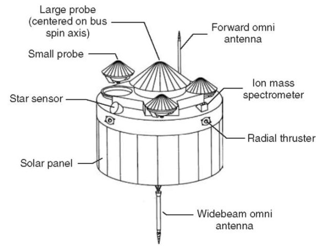
Figure 13. The Pioneer Venus Multiprobe Spacecraft was launched in 1978. It investigated the Venusian clouds and atmosphere by releasing one large probe and three small probes to sample the structure and composition of the clouds, winds, chemical composition, temperature, density, pressure, infrared radiation, and the planet’s interaction with the solar wind.
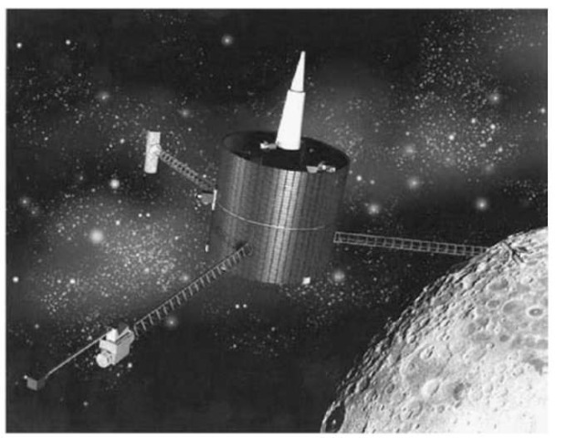
Figure 14. Lunar Prospector’s controlled crash into a crater near the South Pole of the Moon in 1999 produced no observable signature of water, but from Prospector’s data collected during the mission while in orbit, scientists estimate that up to six billion metric tons of water ice may be buried in craters near the Moon’s South and North Poles. Mission findings were also used to develop the first precise gravititational map of the entire lunar surface.
Telecommunications. The telecommunications subsystem provides communication to and from Earth for spacecraft navigation, commanding, and telemetry. Its hardware includes antennae, transponders, and amplifiers. The key functions are signal modulating, demodulation, and some types of data encoding. The key performance parameter is the number of bits per second (bps) that can be transmitted. Among other parameters, the data-rate performance is proportional to transmitter power, the area of the transmitting and receiving antennae, and the square of the transmitting frequency. Planetary-exploration spacecraft use the same Ka-, S-, and X-frequencies as other spacecraft, but there are special frequency allocations for deep space that differ from those for Earth-orbiting spacecraft (25). During the past 25 years, there has been a trend toward higher frequencies for spacecraft telecommunications, from S- to X- and now to Ka-band (32 GHz). Researchers are developing optical communication systems that provide greatly increased performance because of their higher frequency. The current state-of-the-art interplanetary data transmission rate over the Mars range (~ 2 AU) is about 85 kbps, but currently NASA is considering a Mars mission in 2005 that may use a data rate as high as 2 Mbps.
In addition to the primary function of transmitting data to Earth and receiving commands, the telecommunications subsystem is an important element in the navigation system for PES and sometimes is used as part of a scientific investigation. Because of the extreme distances across which planetary spacecraft must be navigated, highly accurate radiometric data are required. To obtain typical accuracy requirements of a few meters for range measurements and 0.1 mm/s for Doppler, a well-calibrated, coherent-ranging transponder is needed. Radio-science experiments use the spacecraft radio and the DSN together as their instrument, rather than using only an instrument aboard the spacecraft. Radio-science experiments record the attenuation, scintillation, refraction, rotation, Doppler shifts, and other direct modifications of the radio signal as it is affected by the atmosphere of planets, moons, or by structures such as planetary rings or gravitational fields. From these data, scientists can derive a great deal of information such as the structure and composition of an atmosphere and particle sizes in rings.
The receiver-acquisition-and-tracking characteristics are unique for planetary spacecraft. Compared to those of typical Earth orbiters, the receiver threshold is very low, the loop bandwidth is very narrow, and the received-signal strength at the ground station is very low, typically as low as —150 dBm. The DSN provides the largest, most sensitive ground stations available in the world, but closing the telecommunications link (both up and down) is still so difficult that the margin left in the link for planetary spacecraft is far less than the typical 10 dB used on Earth orbiters. Planetary-exploration spacecraft use high-gain antennae for communications; they must be pointed to within a small fraction of 1°. The stringent requirements on the telecommunications link for planetary spacecraft have caused the development of sophisticated channel-coding techniques. Coding is a technique using logic and mathematics to help ensure error-free data transmission. One coding scheme that most interplanetary spacecraft use is a forward-error correction scheme called convolutional coding with Viterbi decoding. Another coding technique is Reed-Solomon coding, which adds bits, and is generally imposed before the convolutional code. A recent advance in coding is called turbo code, which may be used on a mission to Mars in 2005. Power. The power subsystem generates, conditions, controls, and distributes onboard power. Power sources may include solar-cell arrays, RTGs, or batteries. Electrical power must be conditioned for particular end users, distributed, made stable, and safely controlled to protect the entire system from power failure. Experience shows that a PES requires a few hundred watts up to about 1 kW of electricity to power all of the computers, radio transmitters and receivers, motors, valves, heaters, data storage devices, instruments, a host of sensors, and other devices.
For a PES going beyond about the orbit of Jupiter, the first power-design question is whether to use RTGs or solar arrays. This decision is based upon the Sun range of the mission, the state of readiness of the various power-source options, the acceptable level of mission risk, safety considerations, and the amount of resources (time and dollars) available to the mission. If RTGs are chosen, spacecraft design dramatically departs from that of Earth-orbiter design. Currently, RTGs contain several kilograms of an isotopic mixture of radioactive plutonium in the form of an oxide pressed into a ceramic pellet. The primary constituent of these fuel pellets is the plutonium 238 isotope. Plutonium 238 emits low-energy alpha particles (which can be stopped by a sheet of paper) and very small amounts of gamma radiation. This, coupled with its relatively long half-life (87.7 years) and high melting point (~2300K), makes it the isotope of choice, even though it is expensive and has a much lower power density (4W/g) than isotopes of cesium, cobalt, and polonium.
The natural radioactive decay of plutonium produces heat (RTGs do not use fission or fusion), some of which is converted into electricity by an array of thermoelectric thermocouples. Thermoelectric conversion does not employ moving components but instead uses the phenomenon of temperature-induced current flow in materials (Seebeck effect). In this system, a pair of dissimilar semiconductor materials (silicon and germanium), where each end is at a different temperature, is joined in a closed circuit to produce a voltage. Unfortunately, the conversion efficiency is quite low (typically 5%), and RTGs radiate to space about 20 watts for every watt of electric power produced. The spacecraft must accommodate this thermal radiation as well as the nuclear-radiation environment. Although gamma rays and neutrons from RTGs pose no SEE threat, they contribute a major part of the total dose to nearby electronic components. These radiation forms are considered “unshieldable” in the sense that no amount of shielding that would be practical on a spacecraft is effective against these particles. Often, some of the IR sensing scientific instruments can be “blinded” by the warm RTG, and a RTG shade is required. Sometimes a cooling system must be included to keep the spacecraft from overheating when it is enclosed in the launch vehicle. The RTG probably must be conductively isolated from the rest of the spacecraft unless the designer tries to use the RTG waste heat to keep the spacecraft warm, which is a good idea, but makes the thermal design of the spacecraft much more complicated than that of an ordinary Earth orbiter.
Besides complicating the design, RTG-powered spacecraft must be compliant with important environmental and safety issues. The National Environmental Policy Act, for example, requires that an impact statement address nuclear-safety risks. Earth-gravity-assist missions must mitigate the possibility of inadvertent Earth reentry and prove that those risks are negligible. Propulsion. The propulsion system provides thrust that is used to maintain three-axis stability, control spin, execute maneuvers, and make minor adjustments in trajectory. The propulsion subsystem includes the engines, propellant tanks, pressurant tanks, and associated valves and plumbing. The larger engines may be used to provide the large torques necessary to maintain stability during a solid-rocket motor burn, or they may be the only engines used for orbit insertion. Smaller thrusters that generate between less than 1N and 10 N are typically used to provide the DV for interplanetary trajectory-correction maneuvers, orbit-trim maneuvers, reaction-wheel desaturation maneuvers, or routine three-axis stabilization or spin control.
The requirements and constraints of planetary-exploration missions make the propulsion subsystem designer pay attention to several special issues. Because navigation is so difficult for planetary missions, unmodeled accelerations, such as those from outgassing and leakage must be avoided, and thrusters should be arranged to provide attitude-control torques in coupled pairs to avoid any translational DV For some missions, scientific objectives drive the choice of propulsion system. Sensitive optical surfaces, cryocooled sensors, and low-temperature thermal radiators are vulnerable to contamination produced by the propulsion system. Spacecraft using such devices require propulsion systems that do not exhaust condensable species that can accumulate on these sensitive surfaces. In some cases, a particular propulsion option is eliminated because a spacecraft instrument is designed to detect the same chemical species that are present in the propulsion-system exhaust.
Trajectories used for some planetary missions often require large maneuvers en route these maneuvers use the primary propulsion system many times in a series of large “burns” required for orbit insertion; insertion can occur years after launch. The primary engine used to deliver the mission DV on a planetary spacecraft may have to operate for up to 10 hours and perform 200 cycles, compared to a similar engine used on an Earth orbiter that may need to operate only for 2 hours and perform 5 cycles. For a planetary spacecraft, the propellant supply and pressurization system may have to last for many years. Earth or-biters, such as GEO-communication spacecraft, use most of their propellant during the first few weeks of the mission, After that, the bipropellant main engine and pressurization system are isolated for the remainder of the mission. The long-life requirement for the propellant supply and pressurization system for planetary spacecraft requires careful consideration of pressurant leakage and interactions between propellant and tankage material, which can lead to blocked propellant lines. To reduce the probability of propellant-line blockage, the Galileo spacecraft bipropellant subsystem is activated routinely to reduce the accumulation of corrosion products (26). The requirement for long storage of the propulsion subsystem in space can drive the requirement for special isolation between the propellants that require using additional pyro-and-latch valves. Lack of proper design and isolation within the bipropellant pressurization system on the Mars Observer spacecraft, was probably a leading cause of its failure (27). The Magellan spacecraft, which orbited Venus, used a large solid-rocket motor (SRM) for orbit insertion. The long duration of “storage” in space caused concern whether the SRM would ignite and burn properly. Earth-orbiter SRMs are fired usually within days of launch.
Because of the large DV required for many planetary-exploration missions, electric propulsion using ion engines has long been viewed as an attractive alternative to chemical propulsion. Ion propulsion using xenon as a propellant has been demonstrated on the NASA/JPL Deep Space 1 spacecraft (28) (Fig. 15). Ion propulsion (29,30) provides an exhaust velocity about 10 times larger than that of a traditional chemical-propulsion subsystem, and therefore it uses only about one-tenth the amount of propellant to provide the same DV. There is a significant savings in propellant, but electric-propulsion systems require additional power-generating and conditioning equipment that offsets to some degree the savings in propellant mass. Interplanetary spacecraft using ion-propulsion systems can undertake the very high DV missions that would be prohibitively massive and therefore expensive using traditional chemical-propulsion techniques.
PES Principles and Margins
The preceding pages have described the key requirements and constraints on planetary-exploration spacecraft and the way those requirements and constraints influence the design of the spacecraft. Although designing planetary-exploration spacecraft is a relatively young art, the practice of this art and the struggle against the requirements and constraints for 40 years and about 20 design cycles have identified some detailed technical design principles (31). These design principles, which are being implemented at NASA’s Jet Propulsion Laboratory, originate in the need for very reliable planetary-exploration spacecraft. This section also includes design margins (31) that have been developed to increase the probability that the spacecraft will be ready to launch (with a high degree of certainty) during the inflexible launch window imposed by solar-system celestial mechanics. In many cases, these principles have been developed in response to past failures (27,32,33).
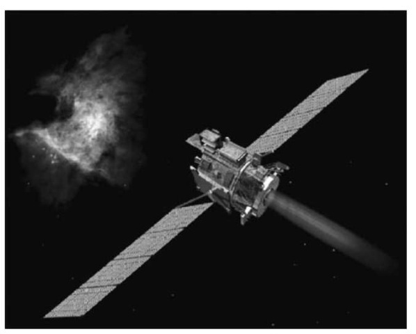
Figure 15. Launched on October 24, 1998, Deep Space 1 was the first mission under NASA’s New Millennium Program, designed to test new technologies for future space and Earth-observing missions. During the primary mission, Deep Space 1 tested 12 advanced technologies and instruments aimed at making future science spacecraft smaller, less expensive, more autonomous, and capable of more independent decision-making so that they rely less on tracking and intervention by ground controllers.
The following principles applied during the design phase help ensure that long-lived spacecraft successfully complete very challenging missions:
* No single electrical and/or mechanical failure shall result in the loss of the entire mission.
* Routine, in-flight power cycling of critical hardware shall be avoided.
* Mission-critical data (flyby science, orbit insertion, etc.) shall simultaneously be recorded onboard and transmitted.
* Thermal design shall keep piece-part, silicon-junction temperatures below 110°C (assuming a 70°C mounting-surface temperature) for circuit design and packaging.
* Electronic hardware shall survive power on/off cycling, temperature cycling, and/or solar exposure cycling of three times the number of worst-case expected mission cycles with worst case flight-temperature excursions. Until a mission estimate is available, the equivalent of 10,000 cycles with a 15°C AT (change in temperature) for new/inherited design hardware shall be used.
* The prime-power distribution hot and return lines shall be DC-isolated from the spacecraft chassis by at least 2 ohms. (This ensures a single fault so that a chassis short anywhere in the distribution system among power source, electronics, or user loads does not pose a catastrophic failure.)
* Prime-power on/off switching of electrical loads shall be done by “simultaneously” switching both hot and return sides. This ensures total load removal (no possible ground-return sneak paths) in case of power-related faults.
* Mission-critical deployable design (for example, solar arrays) shall demonstrate a margin of at least 100% under worst-case conditions, particularly cold, stiff cable bundles, vacuum versus air, and coefficient of friction effects.
* Mission-critical separation design (for example, launch vehicle, probe release) shall demonstrate a margin of at least 100% under worst-case conditions.
* Mission-critical mechanisms and actuator design shall demonstrate at least 100% margin for range-of-motion and the end-of-life stage under worst-case conditions, including restart from within any range-of-motion position.
* All electronic-parts radiative capability shall be at least twice that of the expected end of nominal-mission environment.
* A minimum, prelaunch power-on operating time shall be established for all electronics as follows:
* Unit level prior to spacecraft integration: each electronic assembly, including each side of a block-redundant element, shall have at least 200 hours of operating time.
* System level before to launch: each single-string electronic assembly shall have 1000 hours of operating time. Each side of a block-redundant element shall have at least 500 hours of operating time and a goal of 1000 hours.
Planetary-Exploration Spacecraft Operating Principles. These principles address the most common and critical issues for operating a planetary-exploration spacecraft far from Earth for many years that has only a single opportunity to perform its unique mission.
* All flight-command sequences shall be tested on a high-fidelity, flight-like system test bed, and all anomalies shall be understood and corrected before sequence-uplink transmission.
* After initiation, mission time-critical operations shall not require ”ground-in-the-loop” commanding to enable successful operation/completion.
* Launch-sequence completion shall leave the spacecraft in a ground-commendable, safe state that requires no ”immediate” time-critical ground commanding to assure health/safety.
* After in-flight turn on, the downlink-RF transmitter shall not be turned off during nominal flight operations but shall remain powered during the entire mission, except for momentary power cycling via system-autonomous, fault-protection responses.
* Power cycling of mission-critical hardware shall be avoided.
* Prime-selected hardware elements shall remain in use for all operations.
* Swapping to redundant hardware elements shall be limited to fault-recovery actions to ensure health/safety.
* Stored critical data (for example, launch, fly-by science, orbit insertion, entry/descent and landing) shall be protected from loss in the event of selected anomalies (for example, transient power outage) and shall be transmitted to Earth as soon as practical.
* Mission-critical events (for example, launch-vehicle separation and deployments) and verification of deployables shall be available via real-time telemetry.
* Telemetry and command capability shall be available throughout the mission in normal cruise-pointing attitude and during special cruise-phase mission/ system activities (for example, long-duration, deep-space trajectory correction, maneuvers, and mission-critical propulsion pyrodevice actuations).
* During non-mission-critical cruise periods following a fault condition, the flight-protection response shall at least autonomously configure the spacecraft to a safe, quiescent, ground-commandable state, preferably transmitting engineering status, but at least an RF-carrier downlink signal.
* During critical-mission activities (for example, launch and orbit insertion), the flight fault-protection response shall autonomously reestablish the needed spacecraft functionality to permit safe, reliable, and timely completion of mission-critical activity.
Design Margins. Design margins are intended to keep the spacecraft design, build, and test program on track to meet the launch date. Design margins must be large enough to accommodate design uncertainties/unknowns and still enable design changes with minimal systemwide effects.
* Spacecraft system-level mass margin shall be at least 30% at the project start; 20% at project preliminary design review (PDR), 10% at critical design review (CDR); 5% at assembly, test, and launch operations (ATLO) readiness; and 2% at launch.
* The spacecraft-system-level power margin for cruise, mission-critical, and safing modes shall be at least 30% at project start, 20% at project PDR, 15% at CDR, and 10% at ATLO start.
* At launch, there shall be at least 10% predicted power margin for mission-critical, cruise, and safing-operating modes.
* At the start of the spacecraft design, the computer throughput and memory capability shall exceed estimated requirements by at least a factor of 4.
* The nominal deep-space link margin shall be at least 3 dB.
* Deep-space links with extreme geometry conditions, surface-to-orbit links, or surface-to-surface links shall consider margins of 10 dB or more, depending on the nature, complexity and scope of design uncertainties.


