Introduction
The objective of this article is to provide an introduction to the theory of satellite orbital motion. Although the discussion focuses on Earth-orbiting satellites, the theory is equally valid for computations around other primary bodies including the Moon, the Sun, and the planets. The majority of the discussion focuses on the problem of two bodies. The solution provides sufficient accuracy for many problems in astrodynamics. Perturbations from the two-body problem are discussed because a number of applications require greater accuracy. The solution of these more complex problems is generally accomplished using numerical integration techniques, which is beyond the scope of this chapter. The reader is encouraged to study References 1-7 for a more in-depth treatment of these problems.
Basic Principles of Orbital Motion
The basic principles governing the orbital motion of satellites were first formulated by Johannes Kepler and Isaac Newton in the 1600s. In 1619, Kepler, using the very precise observational data of Tycho Brahe, published what have become known as Kepler’s laws:
1. The orbit of each planet is an ellipse where the Sun is at one focus.
2. The line joining the planet to the Sun sweeps out equal areas in equal times.
3. The square of the period of a planet is proportional to the cube of its mean distance to the Sun.
Kepler’s laws described the kinematics of the motion of the planets, but the dynamic principles describing this motion were not solved until Isaac Newton published the Principia in 1687. Newton’s three laws of motion are given as:
1. Every body continues in its state of rest or of uniform motion in a straight line, unless it is compelled to change that state by forces impressed upon it.
2. The change of motion is proportional to the motive force impressed and is made in the direction of the straight line in which that force is impressed.
3. To every action, there is always opposed an equal reaction, or the mutual actions of two bodies upon each other are always equal and directed to contrary parts.
The Principia also presents Newton’s universal law of gravitation which can be stated as ”any two point masses attract one another with a force proportional to the product of their masses and inversely proportional to the square of the distance between them.” For a satellite orbiting the Earth, this law can be described mathematically as
M is the mass of Earth, m is the mass of the satellite, r is a vector from the center of mass of Earth to the center of mass of the satellite (both of which are assumed to be point masses here), and F is the force acting on the satellite along r.
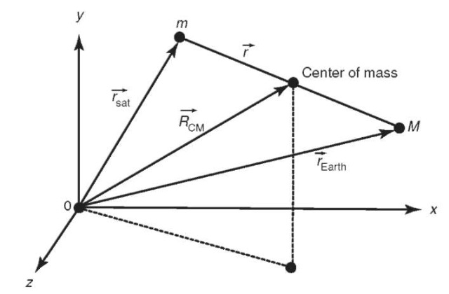
These laws form the foundation upon which our understanding of satellite motion is built. Albert Einstein later explained small differences between observations and Newtonian dynamics, but Newton’s laws provide a remarkably accurate model of satellite motion. The laws include some important concepts that will be used in the remainder of this chapter, including the concept of a point mass m, where all of the mass of a body is concentrated at a single point (or equivalently a uniform sphere), and the concept of an inertial reference frame. The concept of a force F and variable time t are also fundamental to the laws of motion. Two-Body Problem. Newton’s laws of motion and law of gravitation allow us to derive the equations of motion of the satellite with respect to Earth. Using Newton’s law of gravitation and his second law of motion, we can write the equations of motion of Earth and a satellite in an arbitrary inertial reference frame (Fig. 1) as
We can then subtract one of these equations from the other to obtain the equations of motion of the satellite with respect to Earth (but still in the inertial frame):
Figure 1. Derivation of the two-body problem
It is common to ignore the mass of the satellite (as it is quite small with respect
which is a nonlinear, second-order, vector differential equation, often referred to as the ”two-body equation.” It is important to remember the assumptions behind this equation:
1. The mass of the satellite is negligible with respect to the mass of the primary body (Earth).
2. The coordinate system is inertial.
3. Each of the two bodies behaves as a point mass (i.e., they are spherically symmetric and have uniform density).
4. Only the gravitational force between the two bodies is considered; no other forces (atmospheric drag, solar radiation pressure, or gravitational influence of other planets) are present.
Now, we will proceed to develop a solution to this equation, so that we may describe the shape of the satellite orbit about Earth and the position of the satellite in this orbit as a function of time. Let us examine the motion
of the center of mass of the two-body system. The definition of the center of mass is
Combining Equations 2,3 and 6 gives
where A and B are constants of motion. Taking the vector cross-product of r with Equation 5, it may be shown that an object subject only to two-body dynamics has a constant angular momentum vector:
Thus, the angular momentum vector is constant, and the motion of m with respect to M is planar. Taking the dot product of r with Equation 5, we can also show that the energy per unit mass of the motion of m with respect to M is a constant:
where r and v are the magnitudes of the position and velocity vectors, respectively. Also note that this equation represents the sum of the kinetic and potential energy. In summary, we have found 10 integrals of motion (A, B, h, £), and we need to find two more to solve the two-body problem completely.
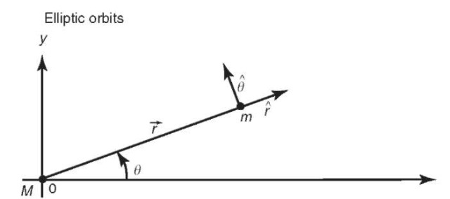
The two-body expression, Equation 5, is one of the few dynamic equations in orbital mechanics that can be solved analytically. Because the orbit of the satellite is planar, we can search for two-dimensional solutions to the problem. It is convenient to express Equation 5 in terms of polar coordinates, as shown in Fig. 2 (for an alternate derivation, see Reference 7). Using the following definitions,
we can rewrite Equation 5 as
First note that Equation 12 can be expressed as
Figure 2. Use of polar coordinates for the two-body problem
This is a simple harmonic oscillator with a solution of
Thus, after transforming variables again, Equation 15 can be written as
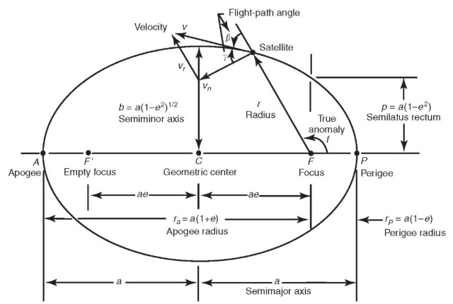
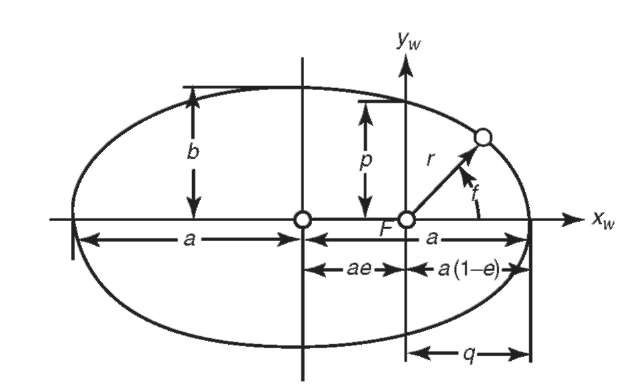
which is the equation of a conic section, either an ellipse, a parabola, or a hyperbola. The size of the conic section is described by the semimajor axis a,and the shape of the conic section is described by its eccentricity e. The position of the satellite on the conic section is described by the true anomaly f, which is the angle of the satellite with respect to periapse (the point of closest approach to the planet). A satellite on an elliptical orbit (0<e< 1,a>0) has been captured by the primary body and will not leave unless otherwise perturbed, and a satellite on a hyperbolic orbit (e>1, a<0), such as a planetary flyby, will never return to the primary body. A parabolic orbit (e = 1, a = oo) is similar to a hyperbolic orbit and not normally encountered except in theory, and a circular orbit (e = 0) is a special case of an elliptical orbit.
For an elliptical orbit, there are some useful equations relating the semima-jor axis a, the semiminor axis b, and the periapse (rp) and apoapse (ra)distances:
An alternative form can be derived for the energy of the orbit in terms of the semimajor axis:
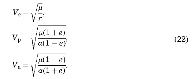
which can be combined with Equation 9 to give a useful expression for the velocity:
For an elliptical orbit, we can derive an expression for the period P of the orbit that is, the time it takes the satellite to make one revolution in its orbit. From Equation 13, we know that the magnitude of the angular momentum vector is
but we also know from calculus that the area swept out by the radius vector as it moves through a given angle is given by
which, combined with the previous equation, gives
which proves Kepler’s second law because h is constant. Integrating this equation over 2p radians of f gives an expression for the orbital period:
which is also an expression of Kepler’s third law.
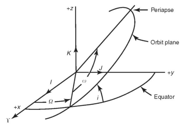
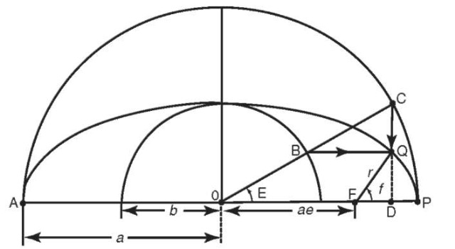
Keplerian Orbit Elements. For an elliptical orbit, the semimajor axis a and the eccentricity e describe the size and shape of the ellipse, respectively, and the true anomaly determines the position of the satellite on the ellipse (Fig. 3). To determine the orientation of the ellipse in inertial space, we need to define three new angles, as shown in Fig. 4. The inclination i of the orbit is the angle between the angular momentum vector and the z axis of the coordinate system (K) (the “tilt” of the orbital plane with respect to the equator). The longitude of the ascending node O is the angle between the line of nodes (the intersection of the plane of the orbit with the equatorial plane) and the x axis of the coordinate system. Finally, the argument of periapse o is the angle between the eccentricity vector (the vector that points toward periapse) and the line of nodes. Together, a, e, i, O, o and f at some time t constitute a set of Keplerian orbit elements that describe perfectly the motion of the satellite around a point mass planet (when coupled with Kepler’s equation in the next section). They can be considered equivalent to knowing the vector position and velocity at some time epoch, which can be used to determine the motion of the satellite by integrating Equation 5. Later, we will discuss how to determine orbit elements from position and velocity vectors and vice versa.
Figure 3. Diagram of an elliptical orbit
Figure 4. Definition of orbital elements.
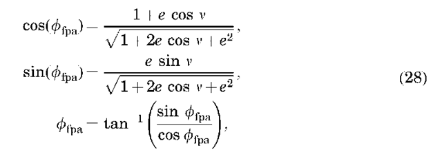
Although not an orbital element, another useful quantity to compute is the flight-path angle. The flight-path angle is the angle between the velocity vector and the local horizontal (as defined by a perpendicular to the position vector), and for noncircular orbits (circular orbits always have a flight-path angle of 0°), the flight-path angle is positive when the satellite is between periapse and apoapse, and negative between apoapse and periapse). It can be computed in the following manner:
where the sine and cosine are explicitly given, so that the inverse tangent may be easily computed without a quadrant check.
Kepler’s Equation. Kepler’s equation allows us to determine the angular position of the satellite in its orbit as a function of time. We will not derive Kepler’s equation here (see Reference 7 among others), however, this can be easily done using Kepler’s second law and by defining a new position angle, the eccentric anomaly E, shown in Fig. 5. The eccentric anomaly is the angle between periapse and the satellite position projected onto an auxiliary circle with respect to the center of the ellipse (Fig. 5). Kepler’s equation relates the eccentric anomaly to the mean anomaly M as
The mean anomaly is not a physical angle like the eccentric and true anomalies; it can only be defined mathematically:
where t is time, tp is the time of the satellite passage of periapse, and n is the mean motion, or the mean angular velocity of the satellite. The mean angular velocity of the satellite around one orbit is simply the orbital period divided by 2p:
Thus, knowing the time past periapse passage and the semimajor axis of the orbit, we can compute the mean anomaly. Using the orbit eccentricity, we can then compute the eccentric anomaly from Kepler’s equation. Finally, the true anomaly can be computed from the eccentric anomaly as
Note that this formulation is valid only for eccentric orbits; different formulations are needed for hyperbolic and parabolic orbits. Also, determining Kepler’s equation for the eccentric anomaly is a nonlinear process, usually accomplished using
Figure 5. Definition of the eccentric anomaly
the Newton-Raphson iteration. If we define a function fE) = M — E + e sin E = 0, we can then expand this function in a Taylor series about some initial guess E0 as
Ignoring higher order terms, we can solve for d as
Because we are ignoring higher order terms, we must iterate the solution for d, and thus a general solution after taking the indicated derivative in Equation 34 is
which should be iterated until E +1 — E;| is less than some prescribed tolerance.
Now, we have the tools to determine the satellite position as a function of time. Of the six Keplerian elements, only f varies with time (for two-body dynamics). At a given time t, we can compute M from Equation 30, and then E and f from Equations 29 and 32.
Computing Orbital Elements From Position and Velocity and Vice Versa. Computations in astrodynamics often require the ability to compute orbital elements from position and velocity vectors and vice versa. This arises because the satellite’s orbital position as a function of time is most easily determined using orbital elements (in an analytical sense—numerical integration techniques work equally well with position and velocity), but other computations, such as determining satellite visibility at a ground station, are most easily accomplished using the position vector.
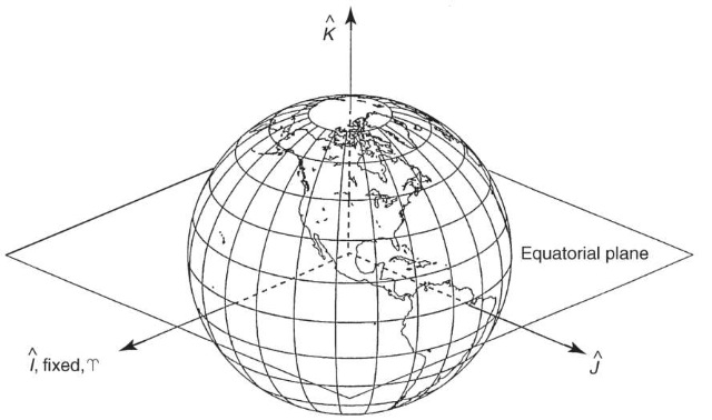
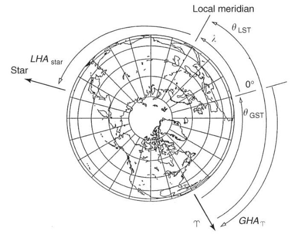
Until this point, we have not talked in detail about coordinate system definitions, but before we discuss the calculation of positional and velocity vectors, we must first define the inertial coordinate system in which they are represented. For Earth-orbiting applications, this is usually accomplished by using a geocentric equatorial system (Fig. 6), denoted here as Earth-centered inertial (ECI) or UK. As shown in Fig. 6, the fundamental plane (IJ) is Earth’s equatorial plane. The I axis points towards the vernal equinox on a particular date (the position of the Sun against the stars as it ascends across the equator near March 21); the K axis points toward the North Pole, and the J axis completes the right-handed system, 90° to the I axis. Currently, the J2000 system, which is a geocentric equatorial frame defined at the J2000 epoch (noon on 1 January 2000), is the most commonly used ECI reference frame. The ECI frame is by definition non-rotating, because it is quasi-inertial. However, for many applications, such as describing the location of tracking stations, we also need to define a body-fixed rotating reference frame. This is typically referred to as the Earth-centered Earth-fixed (ECEF) frame (IJKECEF), where the IECEF axis is pointed at 0° longitude on the equator (the Greenwich meridian), the KECEF, axis points at the North Pole, and the JECEF axis completes the right-handed system (points at 90° longitude). In the absence of the relatively small effects of precession, nutation, and polar motion, the K and KECEF axes are equivalent, and the IJ and IJECEF axes are related through Greenwich sidereal time 9GST (Fig. 7), which is the angle between the I axis and the Greenwich meridian (0° longitude). This angle varies between 0° and 360° as the Earths rotates. Additional rotations are required to account for the effects of precession, nutation, and polar motion (see Reference 7).
Figure 6. Coordinates systems used in the orbit problem.
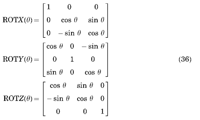
Converting between the ECI and ECEF frames, as well as other conversions we will discuss later, can be accomplished using principal axis rotations which are defined as follows:
where each matrix, when used to premultiply a given vector, will rotate that vector by an angle 9 around the indicated axis. Thus, ignoring precession, nutation, and polar motion, the transformations from ECI to ECEF and back are as follows:
The position of the vernal equinox changes in time, and thus a specific date must be assigned to the equinox used to define the reference frame. A commonly employed reference is the mean equator and equinox of J2000.0. Mean sidereal time accounts for the precession of the equinox, and apparent sidereal time includes secular and periodic motions of the equinox; the difference is referred to as the equation of the equinoxes. Generally, we use Greenwich mean sidereal time, which can be approximately represented as
Figure 7. Relationship between the ECI and ECEF coordinate systems
where 6GST is given in radians, oe is the rotational rate of Earth (7.29211585530 x 10 ~ 5rad/s), AT is the number of Julian centuries elapsed from the epoch J2000.0 (1 January 2000, 12hrs) for the day of interest, and At is the number of seconds from the beginning of the day.
Now, we are ready to describe the transformation of position/velocity to orbit elements and back. Given a vector position r and velocity ~ defined in the ECI frame, we can compute orbital elements using the following procedure.
Position/Velocity to Orbital Elements. The vectors used in this discussion are illustrated in Fig. 4. We can find the semimajor axis using the energy integral (Eq. 9) as follows:
For several reasons, it is convenient to define the eccentricity vector (which points at periapse, Fig. 4) as
The eccentricity of the orbit can be found from the magnitude of the eccentricity vector, or using Equation 16,
The inclination i of the orbit, is the angle between the angular momentum vector and the K axis. Thus using the law of cosines (ab cos a = ~ • b),
The longitude of the ascending node is the angle measured in the equatorial plane from the I axis to the satellite (i.e., it is the angle between I and the node vector ~=Kxh). Thus,
The ascending node may be computed from Equation 43 if a quadrant check is performed (if the y component of the node vector is less than zero, the ascending node lies between 180 and 360°). The argument of periapse a is the angle between the node vector and the eccentricity vector (Fig. 4). Thus,
where again the quadrant must be checked (if the z component of the eccentricity vector is negative, a lies between 180 and 360°). Finally, the true anomaly is the angle between the position vector and the eccentricity vector.
where the quadrant must be checked using the flight-path angle (if ffpa<0, 180° < v<360°). Although these formulas are reasonably general, several special cases can arise that require a different approach, namely, circular and/or equatorial orbits (see Reference 7).
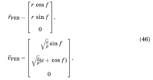
Orbital Elements to Position/Velocity. Orbital elements are best transformed to position/velocity by using the principal axis rotations defined earlier. First, we write the position and velocity vectors as expressed in a “perifocal” reference frame, which has x pointed at periapse, z normal to the orbit plane, and y completing the right-hand system (Fig. 8). In this frame, the position and
Figure 8. The perifocal reference frame.
velocity can be written as a function of orbital elements:
where r is computed from Equation 18 and p = a(1 — e2) is the semiparameter. Once the position and velocity vectors are defined in the perifocal frame, they may be rotated to the ECI frame through simple rotations of — a about z, — i about x, and — O about z, as follows:
In summary, the equations of motion for the two-body problem can be solved and yield a conic section that is best described using Keplerian orbital elements. Given a Cartesian position and velocity for a satellite at a given time, a set of orbital elements may be computed using the preceding equations. These elements may be easily propagated in time because only M varies in time via Kepler’s equation. The propagated elements may be converted back to inertial Cartesian position and velocity using Equations 46 and 47 and into the ECEF frame via Equations 37. The Cartesian position in the ECEF frame is related to geocentric latitude f, longitude l and radius r as
Thus, the latitude and longitude of the satellite may be computed as
It is sometimes also desirable to compute the position of the satellite relative to some fixed point on Earth, such as a tracking site. This can be done by defining a site-fixed topocentric south-east-up (SEZ) reference frame, where the x axis is pointed south, the y axis is pointed east, and the z axis points toward the zenith. Given the Cartesian position of the satellite relative to the site in ECEF frame,
The transformation of a vector from the ECEF frame to the SEZ frame is given as
The azimuth and elevation of the satellite relative to the site are related to the position in the topocentric frame via
and thus the azimuth and elevation may be easily computed as
Perturbation Theory
The discussion to this point has assumed that Earth can be represented by a point mass, that is, a spherically symmetrical homogeneous body, and that no nongravitational forces act on the satellite. In reality, Earth’s shape and mass deviate significantly from a sphere, and a satellite is subject to the significant perturbations of atmospheric drag and solar radiative pressure among other nongravitational forces. The influence of these other effects on the orbit will now be described.
Perturbations Due to Earth’s Nonspherical Shape. The shape of Earth and the distribution of mass within it are quite complex. Normally, we describe Earth’s gravity field in terms of its potential, and then take the gradient of the potential to determine the force on the satellite. For example, the two-body equations, Equation 5, can be expressed in this way:
where VU is the gradient of the potential U. The potential shown here includes only a point mass term. Deviations of the gravity field from a point mass are described by using an expansion of the potential in terms of spherical harmonic functions as
where Pi are the Legendre polynomials of degree i, Pim are the Legendre associated functions of degree i and order m, r is the magnitude of the satellite position vector, f sat and lsat are the satellite latitude and longitude, Re is the radius of Earth (~ 6378 km), Ji are zonal gravitational coefficients describing the latitudinal gravity variations, and Cim/Sim. are the sectorial (i = m) and tesseral (iama0) gravitational coefficients describing the longitudinal gravity variations. The gravitational coefficients are a function of the mass distribution within Earth. The i = 2 terms are related to the moments and products of inertia of Earth as
The J2 term describes the oblateness of Earth, and the J3 coefficient describes its slight ”pear shape.” The i = 1 terms are normally considered zero if the origin of the coordinate system coincides with Earth’s center of mass.
Note that taking the gradient of U in Equation 54 is not trivial because U is expressed in terms of a body-fixed position of the satellite r, f, and l. Thus, the
gradient should be computed in spherical coordinates as
Then, we must rotate this vector quantity from the satellite-fixed polar coordinates to ECEF coordinates and finally to UK inertial coordinates. Thus the final expression for the force of the gravity field can be expressed as
Note that the first term in our expression of the potential (Equation 55) is just the point mass potential, and we know how the orbit behaves in the presence of a point mass. Thus, it is customary to define the disturbing potential and the resulting force due to the nonsphericity of the gravity field as
The gravitational coefficients of Earth (Jl, Clm, Slm) have been determined from tracking observations of artificial Earth satellites (see Reference 8 for a review). The orbital perturbations due to Earth’s gravity field can be classified as either secular (varying linearly in time), short period (approximately the satellite orbital period), and long period (weeks to months). All of these perturbations can be important for some applications, but we will restrict our discussion to secular perturbations because they do not average zero over time. The largest coefficient in the spherical harmonic expansion is the J2 term, which describes the ellipsoidal shape of Earth. Now, we need to describe the technique for determining the effect of J2 on the orbit.
General versus Special Perturbations. To determine how a given perturb-ative force acts on a satellite, one could perform a straight numerical integration of the equations of motion on a computer, referred to in the astrodynamics community as special perturbations, or one could analyze the perturbations using analytical techniques, referred to as general perturbations. The former technique is quite useful for propagating orbits with complex dynamics that do not lend themselves to an analytical treatment, or when an exact representation is required. The latter technique often leads to a more thorough understanding of the effects on the orbit, at the expense of inaccuracies due to linearization of the forcing functions. Some forces are so complex that applying the general perturbation technique is quite unwieldy. The use of the Lagrange planetary equations is a particularly useful general perturbation technique for examining gravitational perturbations.
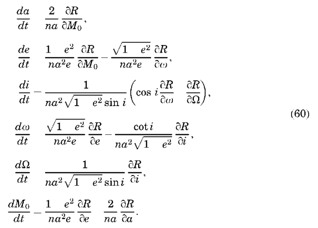
Lagrange Planetary Equations. Most general perturbation techniques rely on a method called variation of parameters. Euler and Lagrange initially developed this method to describe conservative (gravitational) accelerations, and Gauss’ method also applies to nonconservative accelerations. Essentially, these techniques use the two-body orbit as a solution to an unperturbed system and then linearize the perturbations around the unperturbed system. Equations can be developed that describe the secular change of the orbital elements from an unperturbed system. The Lagrange planetary equations present these equations as a function of the disturbing potential R as
Note that these equations require the partial derivatives of the disturbing potential with respect to the orbital elements, whereas the previous expression for the disturbing potential is in terms of satellite position (latitude, longitude, and height). Expressing the disturbing potential R in terms of orbital elements is described by Kaula (9), who used this with the Lagrange planetary equations to investigate gravitational perturbations to the orbit. As the manipulation of the equations is somewhat complex, we will examine the procedure only for J2.
J2 Perturbations and the Secular Precessing Ellipse. As previously mentioned, the J2 gravitational coefficient is by far the most significant term in the definition of the nonsphericity of Earth’s gravity field. The secular effect of J2 on the orbital elements can be determined by isolating this term in the disturbing potential and substituting it in the Lagrange planetary equations. The J2 term of the disturbing potential is
This equation can be expressed in terms of orbital elements using sin fsat = sin i sin(w+f and a trigonometric identity. Because we are interested in secular effects, we can ignore terms containing w and f. If we further average the disturbing potential over one orbital revolution, the final result is (7)
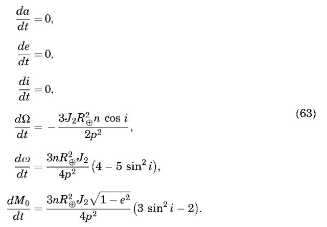
Then, this can be substituted in the Lagrange planetary equations (60) to yield (ignoring higher order terms in J2)
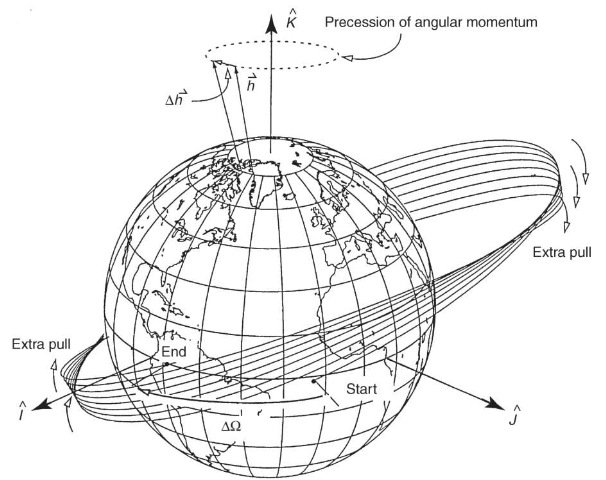
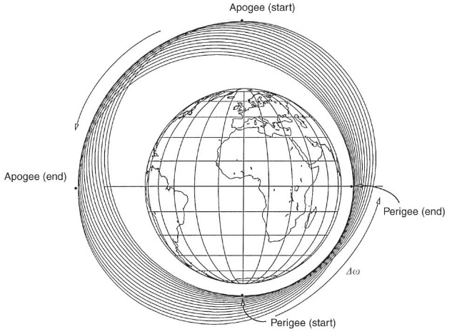
The last equation describes secular changes in the rate of change of the mean anomaly (i.e., changes in the mean motion). The secular changes in the longitude of the ascending node and the argument of periapse have led to the description secular precessing ellipse, as the orbit precesses around the z axis (Fig. 9), and periapse moves around the orbit (Fig. 10). The rate of change of the node can vary by 710°/day, depending on the orbit characteristics. It is zero for a satellite at 90° inclination, and negative/positive for inclinations less/greater than 90°. The rate of change of the argument of periapse can have a similar magnitude and is zero for an inclination of 63.4° or 116.6°, called the critical inclination. Thus, under only the influence of J2, the secular change of the orbital elements can be written as
Figure 9. Precession of the longitude of the ascending node.
Figure 10. Precession of the argument of periapse.
where the other orbital elements (a, e, i) remain constant.
The Lagrange planetary equations are useful only for evaluating conservative forces that can be represented in terms of a potential. There is a Gaussian form of the equations that can be used to study nonconservative forces (7). The evaluation of other perturbations using a general perturbation technique can become quite complex and is beyond the scope of this article. Thus, the remaining perturbations will be described in terms of their contribution to the two-body equations of motion (5), under the assumption that a special perturbation technique (numerical integration) will be used to determine their effect on the orbit.
Perturbations Due to Drag and Solar Radiative Pressure. Atmospheric drag can be one of the largest perturbing forces for low altitude Earth satellites. The drag force per unit mass can be represented as
where p is the atmospheric density, CD is the drag coefficient, Vr is the satellite velocity relative to the atmosphere, m is the mass of the satellite, and A is the cross-sectional satellite area. The quantity in brackets is sometimes referred to as the ballistic coefficient. The atmospheric density drops off approximately exponentially with increasing altitude, and it can have considerable temporal and spatial variation, due to the location of the subsolar point and solar and geomagnetic activity. Commonly used models for the atmospheric density include those in References 10-12. These models commonly use geomagnetic indexes and solar flux values to model the temporal variations of the density. The models are far from perfect, and deficiencies in the models are usually accounted for by estimating the drag coefficient in a piecewise continuous fashion using tracking data. Atmospheric drag is the leading factor that determines the lifetime of the satellite.
Atmospheric drag decreases the energy of the satellite over time, as manifested by decays in the semimajor axis and eccentricity of the orbit. For an eccentric orbit, the periapse radius will remain roughly constant, whereas the apoapse radius decreases over time, corresponding to a decrease in the semimajor axis and the eccentricity of the orbit.
Radiative pressure is also an important force for precise modeling of satellite dynamics. Direct solar radiation is the largest effect, but reflected and emitted radiation from Earth can also be important. The force per unit mass due to solar radiative pressure is given by
where P is the momentum flux from the Sun, us is the unit vector from the Sun to the satellite, A is the cross-sectional area in the direction of us, CR is the reflectivity coefficient whose values are between 1 and 2, and n is a shadow factor equal to 1 if the satellite is in sunlight, 0 if the satellite is in shadow (umbra), and between 0 and 1 if it is in partial shadow (penumbra). Earth radiative pressure can be modeled similarly; however, P would be modified to account for the spatial variations of albedo and emissivity over Earth’s surface. In a manner analogous to drag, satellite reflectivity is sometimes estimated (using satellite tracking data) to account for errors in modeling solar radiative pressure.
Errors in the models for atmospheric drag and solar radiative pressure are quite complex, even when the drag and reflectivity coefficients are estimated. One commonly used method for representing these errors, as well as errors due to other nonconservative forces, is to estimate empirical forces acting on the satellite. Because these orbit errors typically have a frequency of once per orbital period, the form of the empirical force is taken as A + B cos at + C sin at, where a is a frequency of once per revolution and the coefficients A, B, and C are estimated from the tracking data. This force is often represented by vector components in the radial, transverse, and normal directions.
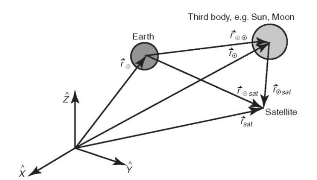
N-Body Perturbations. It is often necessary to include the perturbative effects of other planetary bodies, such as the Moon, Jupiter, and Saturn, in the equations of motion for an Earth-orbiting satellite. This is usually done by considering each of the bodies as a point mass. Using an inertial coordinate system, as shown in Fig. 11, the equations of motion of the satellite with respect to Earth in the presence of a third body can be written as
Newton’s second law and the law of gravitation give
that can be substituted in Equation 67 to yield (after rearranging terms)
We recognize the first term in this equation as the two-body term from Equation 5. The second term represents the perturbation from two-body motion. It is composed of a direct effect, because it is the direct acceleration of the third body on the satellite, and an indirect effect, because it represents the perturbation of the third body on Earth and is not function of the satellite position. We can generalize this
Figure 11. Perturbations due to a third body.
equation from a single third body to N “third” bodies as
This equation may be solved only by using numerical integration techniques (special perturbations), although several integrals do exist (7). For a single third body, the restricted three-body problem (13), where it is assumed that the satellite has no effect on the motion of the other two primary masses and the primary masses move on circular orbits, does have solutions.
Summary. For nonspherical gravitational perturbations only, the time rate of change of the orbital elements may be computed analytically using the Lagrange planetary equations, such as for the secular J2 perturbations to Q, o, and M. However, if a precise representation is needed that includes the effect of non-gravitational forces, direct numerical integration of the equations of motion is best. The expanded equations of motion would be
where Fother might represent relativistic effects, satellite thermal venting, or magnetic effects. Note that for each force component, care must be taken to represent each in a common coordinate system, usually the inertial J2000.0 system.
Types of Orbits
Polar, Prograde, and Retrograde Orbits. Chosing the inclination of an orbit is a critical component of the mission design. Specifying the inclination of the orbit immediately determines the maximum latitude on Earth over which the satellite will pass. When considered in context with Earth’s rotation, the satellite ground track can evolve quite differently if the orbit is prograde versus retrograde. A prograde orbit has an inclination less than 90° (thus the satellite’s motion is in the same direction as Earth’s rotation), and its nodal precession rate (Q) is negative. A retrograde orbit has an inclination greater than 90° (thus it moves in a direction opposite to Earth’s rotation), and its nodal precession rate is positive. A polar orbit has an inclination of 90° and is noteworthy because the orbit plane does not precess due to zonal gravitational perturbations (Q = 0). Equatorial and Geosynchronous Orbits. If the inclination of the orbit is 0°, then it is referred to as an equatorial orbit, and the satellite’s ground track never leaves the equator. A geosynchronous orbit has a period equal to Earth’s rotational period, which implies that it can be obtained by properly selecting the semimajor axis:
Solving for the semimajor axis gives a D 42,164 km to attain a geosynchronous orbit. If the satellite is also in an equatorial orbit, then it stays over the same geographical point on Earth at all times, and the orbit is referred to as geostationary. This is the orbit used by many communications satellites. Sun-Synchronous Orbits. As the name implies, Sun-synchronous orbits maintain a constant orientation of the orbit plane with respect to the Sun throughout the year. This is accomplished by setting the orbit’s nodal precession rate (caused by the perturbations of J2) equal to the angular rate of Earth’s orbit around the Sun of about a degree per day (3607365.25 days = 0.0172028 rad/s). Setting this equal to our equation for the nodal precession rate,
gives an equation for determining the orbital parameters of a Sun-synchronous orbit. For example, for a circular orbit (e = 0.0) at 800 km altitude (a = p = 7178 km), solving for the inclination gives i = 98.6°. This is a common orbit for Earth observation satellites because the solar illumination conditions (i.e., local time) at Earth’s surface are identical each time the satellite passes over the same latitude on the ground.
Other Orbits. A frozen orbit refers to a case where the secular variations of eccentricity and argument of perigee are designed to be zero, so that global variations in altitude are minimized. Orbits whose ground track repeats over a selected period of time are said to have a repeating ground track. These orbits are often used when it is desired to collect measurements over certain locations on the surface of Earth at regular time intervals. The former Soviet Union designed a unique orbit for reconnaissance satellites referred to as the Molniya orbit (after the satellite of the same name). This orbit is characterized by its high eccentricity (0.7), 12-hour period, and critical inclination of 63.4°. The latter allows fixing apoapse over the former Soviet Union to permit long periods of communication.
Orbital Maneuvers
The subject of orbital maneuvers could be a separate article unto itself; however, we can provide an introduction here. We focus our discussion on the Hohmann transfer, the most common technique for transferring a satellite from one orbit to another.
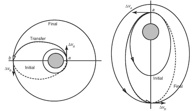
Hohmann Transfer. Hohmann (14) proposed that the minimum-energy transfer between two coplanar orbits could be achieved using tangential burns, where the direction of the velocity change is tangential to the orbit. Hohmann considered only circular orbits, but the theory can be extended to elliptical orbits when the burns are applied at periapse or apoapse (where the flight path angle is zero). Figure 12 demonstrates the geometry of the Hohmann transfer for these two cases. If rinitial is the radius of the lower orbit (or the periapse radius for the elliptical case) and rfinal is the radius of the higher orbit (or the apoapse radius of the final elliptical orbit), the semimajor axis of the transfer orbit and the
Figure 12. The Hohmann transfer.
transfer time can be readily computed:
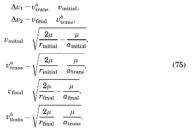
The magnitude of the two velocity changes can then be computed as
A common application of the Hohmann transfer is transferring communications satellites from the initial low Earth orbits, into which they were launched, to their final geostationary orbits from which they operate. Another common application is for interplanetary navigation (e.g., Earth to Mars).
Orbit Determination
A detailed discussion of the subject of orbit determination is outside the scope of this topic. See References 15-17 for a thorough treatment of this topic. However, the concept that we have available an initial position and velocity for the satellite (or equivalently a set of Keplerian elements) is fundamental to much of this article, and thus a brief discussion of the topic is warranted.
The process of orbit determination can be described as developing a dynamic model for a satellite orbit, including its position and velocity at some reference epoch, that best agrees (usually in some least squares sense) with space- and ground-based tracking observations of the satellite. Tracking measurements can be provided in a variety of forms [azimuth/elevation, range, range-rate (Doppler)] and can be made from Earth-fixed tracking stations or from other satellites such as the Global Positioning System (GPS) (18) or the Tracking and Data Relay Satellite System (TDRSS). The tracking observations tend to be nonlinear functions of the satellite position, and the dynamic models that describe the motion of the satellite are nonlinear as well. Thus, the basic approach to orbit determination involves linearizing the measurement and dynamic models, numerically integrating the equations of motion for the satellite using a guess of the initial position/velocity, and then adjusting the state vector (which contains the initial position/velocity of the satellite, drag parameters, gravity parameters, empirical parameters, and tracking station coordinates) to provide the best agreement in a least squares sense between the tracking observations and the numerically integrated orbit. Such a dynamic technique is usually necessary because of gaps in the tracking observations, although new continuous methods such as GPS are allowing implementation of more kinematic methods.
Summary
This article has presented the basic theory for the motion of Earth-orbiting satellites. Although the assumption of two-body dynamics is quite limiting, this theory forms the basic tools used in astrodynamics today. When coupled with general or special perturbation techniques, a high degree of accuracy can be obtained. Indeed, orbit determination accuracies for some Earth satellite missions have approached the few centimeter level (19), as demanded by the science applications.


