18. Compose
My Own Test Equipment
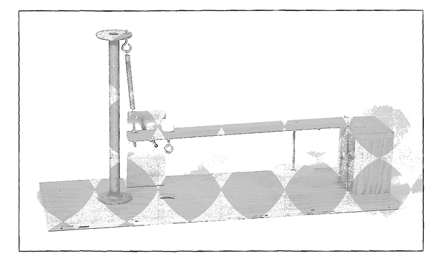
Important note. At the beginning of this topic, I’ve provided a description of my own test equipment so that you understand how my data was gathered. But you do not need equipment like this to test your own motors. In the pages ahead. I’ll show you how to make a homemade test stand and a homemade chart recorder with things you can buy at a hardware store.
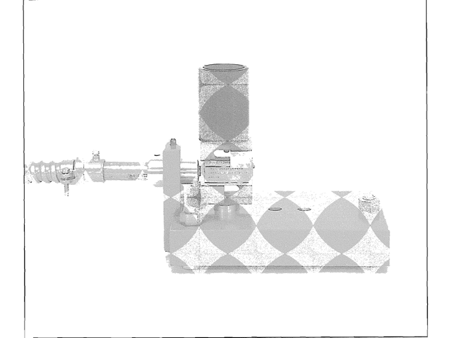
To accurately predict a rocket motor’s flight performance, you need an accurate chart of how its thrust varies with time. In the rocket industry, the accepted way of creating the chart is to have the motor push against a device called a load cell. The load cell outputs to a computer running software that graphs and interprets the data. Figure 18-1 is a photo of the device that I made to gather the data for this topic.

Figure 18-1. The thrust testing stand used to gather the data for this topic. It amounts to motor holder bolted to an S-bar load cell, which is bolted to a heavy block of steel. Data from the load cell feeds through a cable on the left to a computer in my shop.

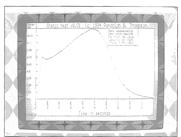
Figure 18-2. Data from the load cell is processed and displayed by a 486 computer set up with an analog-digital board and testing software written by Randy Thompson.
It consists of an S-bar type load cell bolted to a heavy block of steel (painted gray), supported by the heads of three, short bolts that form a sturdy tripod. On top of the load cell is an adapter that holds the motor being tested. The rocket exhaust fires up. the motor pushes down, and the load cell measures the force of the push. A load cell is an electronic device. To protect its cable during a test. I’ve added a bracket on the left that supports a 10 foot length of flexible, steel conduit. The cable passes through the conduit: then out to the amplifier and power supply that make the load cell work.
A load cell is an interesting device. The one in the photo is made of hardened steel, and the central bar of the S has a cavity containing a diamond-shaped printed circuit called a strain gauge. A 10 volt potential is applied between the left and right points of the diamond. When the S is compressed, the diamond is warped. The distortion is only a few-thousandths of an inch, but the stress causes electrical resistances in the sides of the diamond to fall out of balance, and a secondary voltage develops between the top and the bottom of the diamond. The size of the secondary voltage is proportional to the amount of compression, so by measuring this voltage, you can determine the force that caused it.
Load cells are very sensitive, and when properly made, they are accurate to 1/4% of their full scale. They are also very expensive. The one in the photo cost S300. If it were accidentally overstressed. as might happen if a motor exploded, it would be damaged beyond repair. To prevent such damage. I’ve machined two. small aluminum blocks, and placed them between the bars of the S. They act as stops to keep the load cell from being compressed beyond its design limits.
A d.c. electric current is provided by an accurate and steady power supply. The tiny, secondary voltage is boosted by an amplifier, then sent to an analog-digital board in a 486 computer (Figure 18-2). The force vs. time data is graphed and printed: then saved in both ASCII data and XY file formats. The testing software, written for me by Randy Thompson, can be zeroed for a motor of any weight, and calibrated for any load cell. It can even compensate for a damaged load cell that doesn’t give accurate readings.

Figure 18-3. A homemade thrust-testing stand. The one in this photo is suitable for testing motors up through F.
