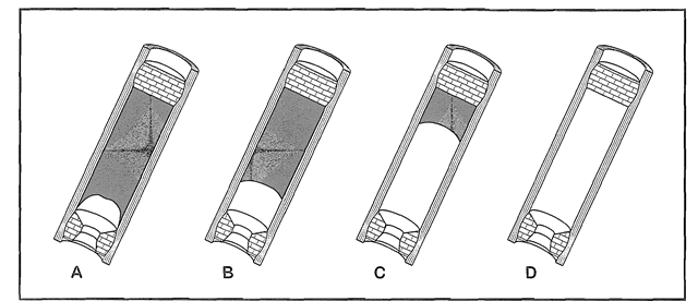
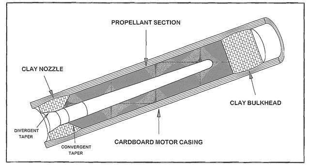
The simplest grain geometry is a solid, cylindrical stick of propellant with its sides sealed tightly to the casing wall. To facilitate ignition, a small dimple is formed in the grain’s rear end. just big enough to accept an igniter. Figure 2-2 is a cutaway drawing of one of these motors. It’s called an end burner, and Figure 2-3 shows what happens when it burns.
Immediately after ignition the flame spreads outward in the form of a hemisphere with a surface area greater than the propellant grain’s cross section. This creates an initial surge of high pressure and high thrust that quickly diminish as the shape of the burning surface changes into a shallow cup. At that point the pressure and thrust level off. and should theoretically remain constant for the rest of the burn.
When properly made, end burners produce a constant level of thrust for a comparatively long time. But they have the disadvantage that the inside wall of the casing is exposed to open flame for the duration of the burn. Because the casings for the motors in this topic are made of paper, the implications are obvious. If you make the burn time too long, you’ll burn through the casing wall. Also, for the chamber pressure and thrust to remain constant, it is absolutely imperative that an end burner’s propellant burn at a perfectly uniform rate.
Small end burners made with homogeneous propellants work fairly well. But as end burning propellant grains are made larger, their cup-shaped burning surfaces grow increasingly uneven. This phenomenon is called “cavitation”. It happens regardless of how evenly the propellant is mixed, and it causes unacceptable variations in chamber pressure and thrust. When building a large rocket motor, the solution is to adopt a core burning configuration. Because rocket engineers understand this well, all of the larger commercial and military solid fuel motors, including the giant boosters on the Space Shuttle, use some variation of the core burning design.
Time constraints involved with the publication of this topic, a possibly unsolvable engineering problem, and difficulty in obtaining the proper cardboard tubes prevented me from developing a workable end burner. But I was able to develop the tooling and the basic method of construction for those who want to experiment on their own. I discuss end burners at length in topic 10.

Figure 2-3. The flame in an end burner travels in a straight line from the point of ignition to the forward bulkhead. The dome-shaped flame front, formed immediately after ignition, generates a surge of high pressure and high thrust. As the dome changes into a shallow cup. both chamber pressure and thrust are reduced, and thereafter remain constant.

Figure 2-4. A cutaway drawing of a cylindrical core burner. A cylindrical core burner has a
End Burners (Rocket Motor)
Next post: Cylindrical Core Burners (Rocket Motor)
Previous post: Basic Terminology (Rocket Motor)
