UMTS leveraged several industry-standard, established protocols. This includes CC, MM, SM (GSM), GTP (GPRS), BICC, SS7, SS7-over-IP/ATM, UDP, IP, and others. However, new protocols have been developed for the UTRAN interfaces. Section 5.4.1 introduces protocol structure at the new Iu interfaces. The detailed specifications for each of these protocols are available from the 3GPP website. Section 5.3.1 describes these protocols in brief.
UTRAN interfaces and protocol structure
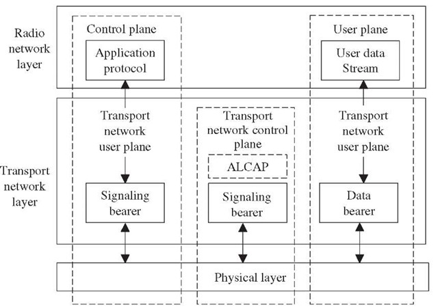
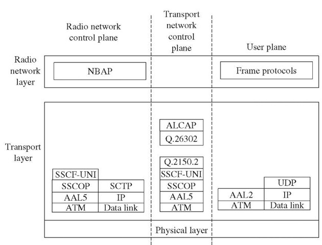
Figure 5-4 shows the general protocol model for UTRAN interfaces, i.e. Iub, Iur, Iu-CS, and Iu-PS. The structure consists of two horizontal layers: the Radio Network Layer and the Transport Network Layer.
The Radio Network Layer is concerned with user data and control information. The Transport Network Layer is concerned with the transport technologies used for the UTRAN interfaces. The two layers are logically independent of each other. This makes it possible to change the Transport Network Layer without affecting Radio Network Layer, if required. In Release 99, the Transport Network Layer is based on ATM. In Release 5, IP is used.
Figure 5-4 Generic protocol model for UTRAN interfaces.
The user plane includes the user data between the UE and the network and the data bearers. The user data consists of data streams characterized by frame protocols specific to a UTRAN interface.
The control plane includes the application protocols and the signaling bearers, which transport the control information. The application protocols used at different UTRAN interfaces are:
■ Iu-CS: Radio access network application protocol (RANAP)
■ Iu-PS: RANAP
■ Iub: Node B application protocol (NBAP)
■ Iur: Radio network system application protocol (RNSAP)
The transport network control plane includes the access link control application protocol (ALCAP). ALCAP is used to set up transport bearers to carry user and control plane information. It is not visible to the Radio Network Layer.
Several alternatives are available for the Physical Layer implementation within UTRAN. The specified options in 3GPP release at Iu interfaces are:
■ Layer 1 synchronized option, i.e., PDH/SDH/SONET.
■ Layer 1 IP nonsynchronized option, i.e., Ethernet or any other suitable point-to-point or point-to-multipoint technique.
Iu-CS interface protocol structure. In UMTS, the interface between RAN and CN is Iu. Iu-CS is the interface specified between the RAN and the 3G MSC. The Iu-PS interface is defined between the RAN and the 3G SGSN. In order to have uniformity, 3GPP specifies a single protocol at Radio Network Layer for the Iu-CS and the Iu-PS interfaces. The radio access network application protocol (RANAP) is the Radio Network Layer protocol for the Iu interface. The RANAP peer entities reside in 3G MSC/SGSN and the SRNC. The RANAP functions are specified in 3GPP TS 25.413 in detail. In summary, RANAP procedures support the following key functions.
■ Radio access bearer (RAB) management including RAB setup, modification, and release
■ Iu connection management
■ Facilitate general UTRAN procedures from the core network, e.g., paging requests from the CN to UE
■ Services to upper layers including the transportation of upper layer nonstratum protocols (i.e., call control, session management, and mobility management) messages between the UE and CN
■ Overload and error handling
■ SRNS relocation
■ UE location reporting
■ Trace invocation for a specified UE
■ Security functions including ciphering and integrity checks
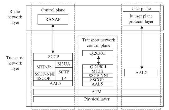
RANAP uses services provided by the Transport Network Layer to transfer RANAP messages across the Iu interfaces. Figure 5-5 shows the Transport Network Layer protocol stack. The transport layer ensures error free message transfer between two RANAP entities. The Service Connection and Control Part (SCCP) offers both connectionless and connection-oriented services. Each active UE is assigned a separate logical link in case of connection-oriented service between two RANAP entities. The SCCP utilizes services provided by the lower layers to transport messages between two entities. Layer 3 Broadband Message Transfer Part (MTP3b) provides message routing, discrimination, and distribution. It also provides link management functions including load sharing between linksets. The SSCF maps the requirements of above layers to the requirements of SSCOP. The SSCOP provides the mechanism for the establishment and release of connections and the reliable exchange of signaling information between the signaling entities. In cases where the IP transport option is chosen, the services are provided by M3UA, SCTP, and IP. AAL5 is used to adapt the upper layer protocol to the requirements of the lower ATM cells.
The radio network layer—Iu user plane protocols carry the user data over the bearers that are set up by the Transport Network Layer.
Figure 5-5 Iu-CS interface protocol structure.
The frame protocol in the Iu interface supports both CS and PS domain user data traffic.
As described in the previous section, the purpose of the transport network control plane is to set up, maintain, and release bearers to transport the data via the user plane. The AAL2 signaling protocol capability set 1 (ALCAP), which is described in ITU-T specification Q.2630.1, is used. ALCAP is a Layer 3 protocol. Its responsibility is to set up and manage ATM Adaptation Layer 2 (AAL2) connections.
In the user plane, ATM Adaptation Layer 2 (AAL2) is used as the user data bearer. AAL2 has been specifically designed to transport short-length packets.
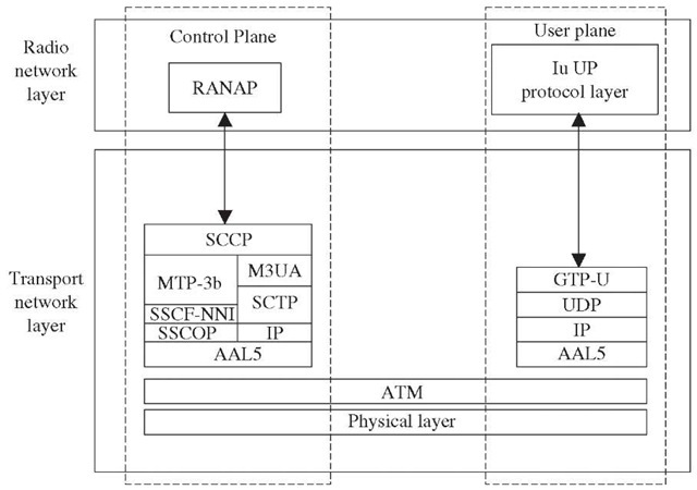
Iu-PS interface protocol structure. The Iu-PS interface is specified between the RAN and the 3G SGSN (Figure 5-6). As described in the previous section, 3GPP specifies a single protocol at the Radio Network Layer for the Iu-CS and the Iu-PS interfaces, i.e., RANAP for the control plane and Iu for the user plane. Both of these are defined in the previous section.
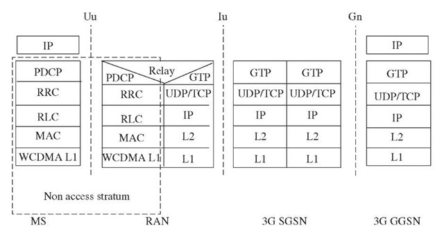
No transport network control protocol is needed. Unlike GPRS, where the GTP tunnel ends at the SGSN, the GTP tunnel in UMTS extends up to RNC. The tunnel ID and IP address, which is required to establish a tunnel, is included in the upper layer protocols.
Like GPRS, GTP-U uses UDP/IP. AAL5 is used to carry the packet-switched user traffic over the Iu-PS interface.
Figure 5-6 Iu-PS interface protocol structure.
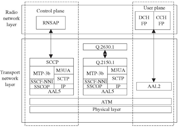
Iur interface protocol structure. Iur is the interface between the RNCs (Figure 5-7). One of the RNCs assumes the controlling role and is termed the serving RNC (SRNC); the other RNC is termed the drifting RNC (DRNC).
The Radio Subsystem Application Part (RNSAP) is a Radio Network Layer protocol used at the Iur interface. RNSAP includes procedures for network control signaling between two RNC nodes:
■ Radio link management and reconfiguration
■ Radio link supervision
■ Common control channel (CCCH) signaling transfer
■ Paging
■ Relocation execution
RNSAP uses the services of the Transport Layer for reliable transfer of signaling messages in both connectionless and connection-oriented modes. The SCCP allows a separate independent logical connection with individual UE. If the ATM transport option is chosen between two RNCs, the SCCP uses MTP3-B, SSCF-NNI, and SSCOP services for networking and routing of messages. In cases where the IP transport option is chosen, these services are provided by the M3UA, SCTP, and IP.
Figure 5-7 Iur interface protocol structure.
Iub interface protocol structure. Iub is the interface between the Node B and the RNC (Figure 5-8).
The Node B application protocol (NBAP) is a Radio Network Layer control plane protocol at the Iub interface. NBAP includes the procedures to manage the logical resources at Node B. NBAP procedures support the following functions:
■ Cell configuration management
■ Radio link management and supervision
■ Common transport channel management
■ System information management
■ Configuration verification/alignment
■ Measurement of common and dedicated resources
System network protocols
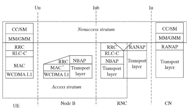
Access and nonaccess stratum protocols. The Access Stratum (AS) is defined as the group of protocols (all layers) embedded in the UTRAN and between the edge nodes (UE and RNC). The Nonaccess Stratum (NAS) is defined as the group of protocols between the UE and the CN. These protocols are carried transparently through the UTRAN. Figures 5-9 and 5-10 show the Access Stratum and Nonaccess Stratum protocol boundaries in the control and user planes, respectively.
Figure 5-8 Iub interface protocol structure.
Figure 5-9 Control plane protocols.
Figure 5-10 User plane protocols.
RAN protocols (Access Stratum) are described in the previous section. The protocols belonging to the Nonaccess stratum group are:
■ CS domain
■ Call control management (CC)
■ Mobility management (MM)
■ PS domain
■ Session management (SM)
■ GPRS mobility management (GMM)
The call control management protocol contains the functions and procedures for call establishment, monitoring, and release for circuit-switched voice and multimedia calls.The mobility management protocol includes procedures for UE mobility and authentication. As shown in Figure 5-9, the CC protocol uses the connection service provided by the MM sublayer. The MM sublayer in turn uses the connection services provided by the Radio Resource Connection (RRC) Layer. The RRC handles the control plane signaling of Layer 3 between the UE and UTRAN. It establishes, maintains, and releases the signaling connection and radio bearers for UE on request from the upper layer. The RNC uses the relay functionality to map the CC messages into RANAP for forward transmission to core network.
Like the CC protocol, the session management protocol is used to activate, modify, and delete PDP contexts. The prerequisite to a SM context for a UE is the existence of a GMM context. The GMM includes the functions and procedures for the UE mobility and authentication procedure in the PS domain.
