GSM Interfaces and Protocols (Global System for Mobile Communication (GSM)) Part 3

A interface

The A interface is the interface between the BSC and the MSC. At the physical layer, it uses a 2-Mbps PCM30 link. One or more 64-Kbps timeslots are used to carry signaling information. Typically, more than one 2-Mbps link is required to handle the traffic between the BSC and the MSC.

The Base Station System Application Part (BSSAP) is a GSM-specific protocol designed for signaling over the A interface. The BSSAP uses CCS7 MTP and SCCP transport and addressing services for the signaling message transfer. The BSSAP supports both connectionless and connection-oriented services provided by the SCCP. The connectionless services are used to support global procedure such as PAGING (for MS) and RESET (a circuit). The connection-oriented services are used for dedicated procedures such as handover and assignment procedures. The BSSAP supports messages sent between the MSC and the BSS, as well as transparent message transfer between the MSC and the MS. To enable this functionality, the BSSAP is divided into two parts, i.e., the Base Station Subsystem Management Application Part (BSSMAP) and Direct Transfer Application Part (DTAP).

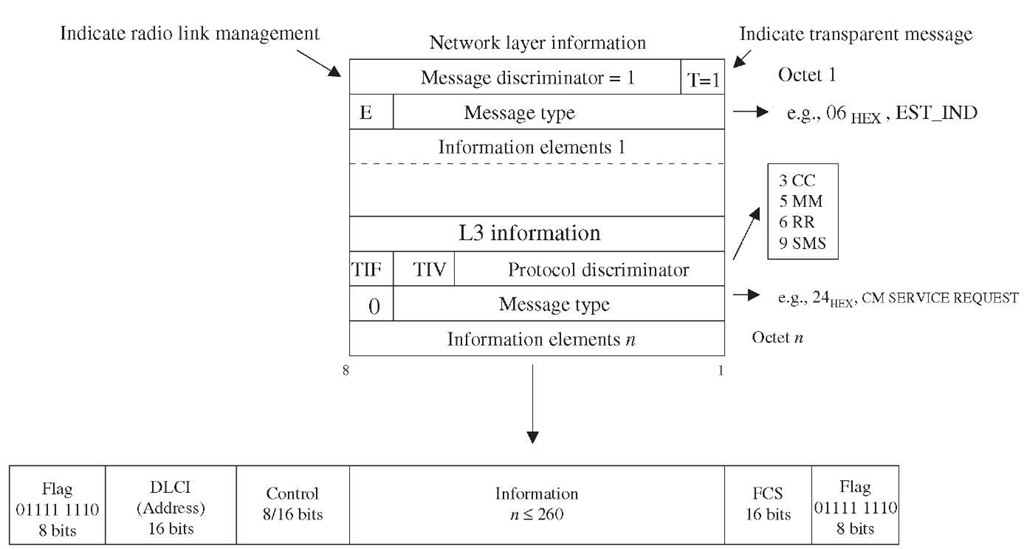
Transparent Layer 3 message over Abis.


Figure 3-17 Transparent Layer 3 message over Abis.

TABLE 3-10 Abis Layer 3 Messages

RLM

CCM

TRXM

DCM

DATAREQuest

BCCH

RF REsource

CHANnel ACTivation

INFOrmation

INDication

DATAINDication

CCCH LOAD

SACCH

CHANnel ACTivation

INDication

FILling

ACKnowledge

ERROR

CHANnel

OVERLOAD

CHANnel ACTivation

INDication

REQuired

Negative ACKnowledge

ESTablish

DELETE

ERROR

CONNection FAILure

REQuest

INDication

REPORT

INDication

ESTablish

PAGING

DEACTivate SACCH

CONFirm

CoMmand

ESTablish

IMMEDIATE

ENCRyption CoMmand

INDication

ASSign CoMmand

RELease

SMS Broadcast

HANDOver DETection

REQuest

REQuest

RELease

MEASurement RESult

CONFirm

RELease

MODE MODIFY

INDication

REQuest

UNIT DATA

MODE MODIFY

REQuest

ACKnowledge

UNIT DATA

PHYsical CONTEXT

INDication

REQuest

PHYsical CONTEXT

CONFirm

RF CHANnel RELease

MS POWER

CONTROL

BS POWER

CONTROL

PREPROCess

CONFIGure

PREPROCessed

MEASurement RESult

RF CHANnel RELease

ACKnowledge

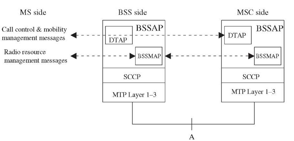
Figure 3-18 illustrates the protocol stack on the MSC and the BSC side. The MM and CM sublayer signaling information from the MS is routed to the BSS transparently over the signaling channels (FACCH, DACCH, SACCH). From the BSS, this information is relayed to the MSC by DTAP. The DTAP uses SCCP logical connection to transfer the information to the peer MM or CC entity in the MSC.

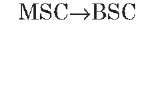
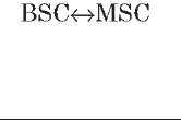
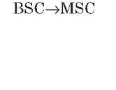
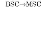
BSS management application part. The BSSMAP data are part of Layer 3 and carry messages related to radio resource and the BSC management. The BSSMAP process within the BSC controls the radio resources in response to the instructions given by the MSC. Examples of BSSMAP messages are paging, handover request, reset, and block. Table 3-11 lists the BSSMAP messages.

A-interface signaling protocol.

Figure 3-18 A-interface signaling protocol.

Direct transfer application part. The DTAP data is user information and carries messages related to call control and mobility management between two users, i.e., MS and any subsystem of NSS such as the MSC. The messages are transparent to BSS except for a few exceptions. These exceptions are location update request, CM service request, and IMSI detach indication. These messages are partially processed by the BSC to add necessary information required for other entities to process these requests.

The DTAP messages are identical to the transparent MM and CM messages listed in the previous section.

Inter-MSC signaling

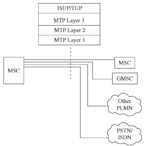
For call control, an MSC may have signaling interfaces to other MSC, GMSC, PLMN, and PSTN. Figure 3-19 shows the protocol stack used on these interfaces. ITU-T ISUP or TUP protocol is used for call setup and supervision. TUP is an old protocol and may not be used in newer implementations. ISUP is used for both speech and data call setup. ISUP relies on the MTP protocol for transportation, addressing, and routing of call control messages.

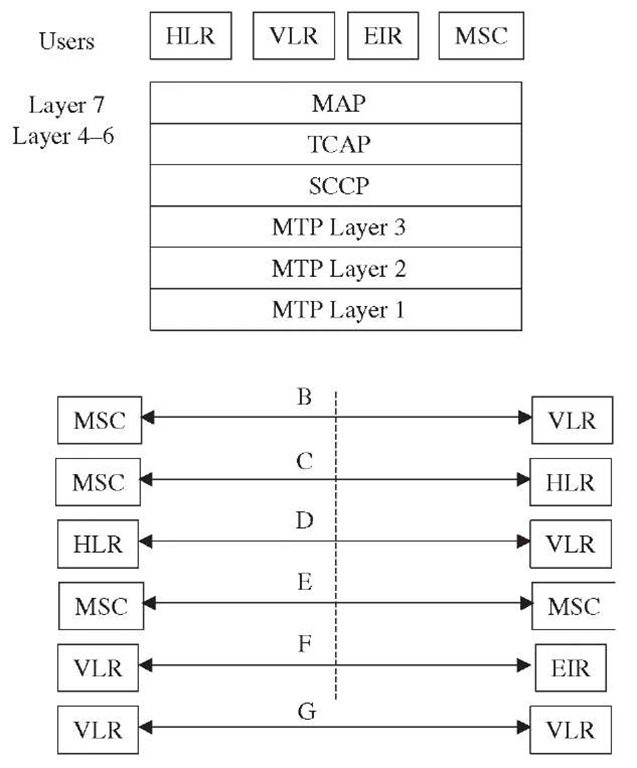
The MSC also has interfaces with the VLR, HLR, EIR ,GMSC, and interworking MSCs for non-circuit-related call control. Figure 3-20 shows this interface and protocol stack. The GSM Mobile Application Part (MAP) has been specifically designed for transfer of non-circuit-related signaling information between MSCs and between MSCs and databases. MAP relies on TCAP capabilities to establish non-circuit-related communication between two entities in the signaling network to exchange data and control information.

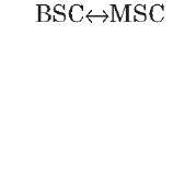
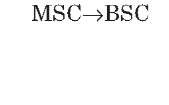
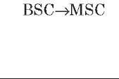
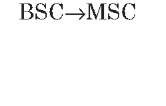
TABLE 3-11 BSSMAP Messages

Message type

ID (hex)

Direction

Remarks

Assignment messages

Assignment request

01

tmp23-86

ASS REQ is sent from the BSC to the MSC to request a traffic channel on A and air interface.

Assignment complete

02

tmp23-87

ASS COM is a positive response from the BSC.

Assignment failure

03

tmp23-88

ASS FAIL is a negative response from the BSC.

Handover messages

Handover request

10

tmp23-89

The MSC sends HND REQ to the new BSC that is the target for handover.

Handover required

11

tmp23-90

The BSC sends HND RQD to the MSC in case of inter-BSC or inter-MSC handover.

Handover request acknowledge

12

tmp23-91

HND REQ ACK is the acknowledge for the previously received HND REQ.

Handover command

13

tmp23-92

HND CMD provides the information to the BSC related to the new radio channel resource to which the MS should switch.

Handover complete

14

tmp23-93

HND CMP indicates successful handover

Handover failure

16

tmp23-94

HND FAIL indicates unsuccessful handover.

Handover performed

17

tmp23-95

HND PERF indicates that the BSC has performed the intra-BSC handover.

Handover candidate enquiry

18

tmp23-96

HND CND ENQ is sent by the MSC to get the list of MSs in a particular cell that could be handed over to another cell to reduce the load on a target cell.

Handover candidate response

19

tmp23-97

HND CND RES is a response to the HND CND ENQ message.

Handover required reject

1A

tmp23-98

HND RQD REJ indicates an unsuccessful response to HND_RQD message.

Handover detect

1B

tmp23-99

The BSC sends HND DET to the MSC updating changes in the radio resource on receiving the HND DET message from the BTS.

Release messages

Clear command

20

tmp23-100

CLR CMD is used to release a traffic channel allocated to a specific MS.

TABLE 3-11 BSSMAP Messages

Message type

ID (hex)

Direction

Remarks

Release messages

Clear complete

21

tmp23-101

CLR CMP is the confirmation of resource release in response to CLR CMD message.

Clear request

22

tmp23-102

The BSC sends CLR REQ to the MSC on detecting any severe problem with an existing connection to an MS.

SAPI "n" reject

25

tmp23-103

The BSC sends SAPI REJ message to the MSC on receiving a message with SAPI not equal to zero but for which no Layer 2 connection exists.

Confusion

26

tmp23-104

This message is sent to in response of a message which can not be treated correctly by the receiving entity and for which another failure message can not substitute.

General messages

Reset

30

tmp23-105

Send by the MSC to the BSC (or vice versa) if the sending entity detects any fatal error in communication data.

Reset acknowledge

31

tmp23-106

RES ACK is sent to confirm that the RESET message was received.

Overload

32

tmp23-107

The BSC sends overload message to indicate the overload situation in a BTS or whole BSS. The MSC sends overload message to the BSC to indicate processor overload within the MSC.

Reset circuit

34

tmp23-108

RES CIRC is used to initialize a single circuit between the BSC and the MSC.

Reset circuit acknowledge

35

tmp23-109

Response to RES CIRC on a successful reset of a circuit.

MSC invoke trace

36

tmp23-110

Request to start a trace of a single connection. MSC INV TRC will enable tracing of messages in the direction from MSC to BSC.

BSS invoke trace

37

tmp23-111

Request to start a trace of a single connection. BSS INV TRC will enable tracing of messages in the direction from BSC to MSC.

Terrestrial resource messages

Block

40

tmp23-112

The BSC requests the MSC to block a single channel, using BLO message.

Blocking acknowledge

41

tmp23-113

The MSC acknowledges the blocking of a channel by sending BLO ACK message to the BSC.

Unblock

42

tmp23-114

UNBLO message is used to cancel the blocking.

TABLE 3-11 BSSMAP Messages

Message type

ID (hex)

Direction

Remarks

Terrestrial resource messages

Unblocking acknowledge

43

tmp23-115

Acknowledgment of BLO message.

Circuit group block

44

tmp23-116

The BSC requests the MSC to block the multiple channels or complete PCM link, using CIRC GRP BLO

message.

Circuit group blocking acknowledge

45

tmp23-117

The MSC acknowledges the blocking of the multiple channels/complete link by sending CIRC GRP BLO ACK message to the BSC.

Circuit group unblock

46

tmp23-118

CIRC GRP UNBLO message is used to cancel the blocking of multiple channels or complete PCM link.

Circuit group unblocking acknowledge

47

tmp23-119

Acknowledgment of CIRC GRP UNBLO message.

Unequipped circuit

48

tmp23-120

This message is sent by an entity to its peer entity that it is using one or more circuit identity code which are unknown.

Radio resource messages

Resource request

50

tmp23-121

The MSC requests the BSC to provide information on available radio resources.

Resource indication Paging

51

52

tmp23-122

Response to RES REQ. The MSC sends this message to locate the MS in case of MTC.

Cipher mode command

53

tmp23-123

The MSC sends a CIPHER MOD CMD to the BSC to instruct to start ciphering on air interface.

Classmark update

54

tmp23-124

The MS sends CLS MRK UPD to the MSC via BSC to update the classmark changes, if any.

Cipher mode complete

55

tmp23-125

The BSC sends this message to the MSC in response to the previously received CIPH MOD CMD to indicate that ciphering has successfully initiated on air interface.

Queuing indication

56

tmp23-126

Indicates the delay in assignment of traffic channels because of no availability of resources in response to previously received ASS REQ or HND REQ.

Complete Layer 3 information

57

tmp23-127

The CL3I message contains the initial message received from the MS for which SCCP connection at A interface can be set up. The typical example of such an initial message is CM SERV REQ.

Classmark request

58

tmp23-128

This requests MS to send its classmark information.

Cipher mode reject

59

tmp23-129

An unsuccessful response to the previously received CIPH MOD CMD.

An unsuccessful response to the previously received CIPH MOD CMD.

Circuit-switched call—protocol stack.

Figure 3-19 Circuit-switched call—protocol stack.

Noncircuit call control protocol stack.

Figure 3-20 Noncircuit call control protocol stack.

TCAP in turn relies on SCCP addressing and MTP transport capabilities.

MAP is also used between the VLR and the HLR. The B interface between the MSC and the VLR is an internal interface in most of the implementations.

The communication between applications and the MAP is done via MAP services or local operation codes defined in the GSM MAP specification. Table 3-12 lists local operation codes and their functions.

The local operation codes defined for the MAP operation on the B interface (MSC-VLR) are not listed in Table 3-12. The B interface is an internal interface and is not visible in most implementations. The GSM recommendations do not encourage the use of this interface and have not updated specifications for this interface since Release 99.
Next post:

Previous post: