Remote sensing is a field of technology designed to enable people to look beyond the range of human vision. Whether it is over the horizon, beyond our limited human range, or in a spectral range outside human perception, we are in search of information. The focus here will be on imaging systems that extend our range of perception, particularly in the realms of intelligence, strategy, tactics, and military applications.
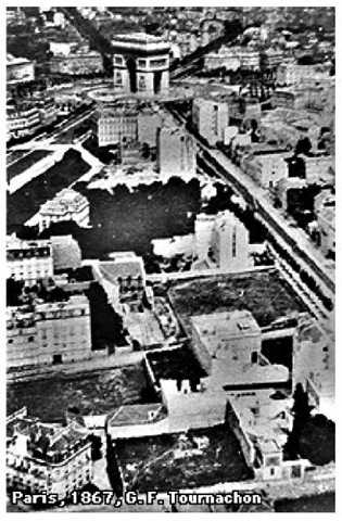
To begin, consider one of the first remote-sensing images. Figure 1.1 shows a photograph by Gaspard-Felix Tournachon1 (Gaspard was also known by his pseudonym, Nadar). Gaspard took this aerial photo of Paris in 1868 from the Hippodrome Balloon, tethered 1700 ft above Paris. Contrast this with the cover photo taken by Apollo 17, just one hundred years later.
This is a fairly classic remote-sensing image—a representation from a specific place and time of an area of interest. What sorts of things can be learned from such an image? Where, for instance, are the streets? What buildings are there? What are the purposes of those buildings? Which buildings are still there today? These are the elements of information that we want to extract from our imagery.
Figure 1.1 Nadar took his first aerial photographs in 1858, but those earlier images did not survive.2 Nadar applied for a patent for aerial surveying and photography in 1858. Aerial reconnaissance followed shortly, with significant work during the American Civil War.3
In the material that follows, a model is established for extracting information from remote-sensing data. Following that section, remote-sensing data from a variety of systems is introduced to provide an early overview of the domains of the field.
Remote-sensing data, sans analysis, have a fairly modest value. What is really wanted, in general, is information appropriate to making a decision. To the extent we can obtain or understand what information can be derived from remote-sensing data, we begin to address a question posed in the preface: What is remote sensing good for? To answer, a paradigm is introduced, termed "order of battle" (OOB). This is largely associated with the counting of "things," but not entirely. Indeed, one thing for which care must be taken: don’t limit the levels of information to simple "counting." We also need to pay attention to nonliteral forms of information.
OOB has a number of forms, depending on the area of interest, as indicated here:
Air order of battle (AOB)
Cyber order of battle (COB)
Electronic order of battle (EOB)
Ground order of battle (GOB), including logistics
Industrial order of battle (IOB)
Naval order of battle (NOB)
Space order of battle (SOB)
What items characterize these OOB types? What sort of information are we considering? Taking GOB as an example, one might like to know about vehicles—their numbers, locations, and types. Examples of types would be armored (e.g., tanks), transport (trucks), and personnel (high-mobility, multipurpose, wheeled vehicles, or HMMWVs). Having established types, further elements of information include operational status (fueled, hot, armed), capabilities, and armament (weapons). Other elements of GOB are troops (numbers, arrangement, types), defenses (for example, minefields, geography, missiles, chemical/biological, camouflage, and decoys) and infrastructure (such as roads and bridges). Three other OOB examples follow.
Figure 1.2 SR-71 image, Bluefields, Nicaragua, New runway under construction, 2 January 1982.
Air order of battle
For air order of battle (AOB), the focus is primarily on aircraft and airfields. A tabular approach to compiling salient elements of information is shown below. The table is organized in increasing level of detail. There are several levels of detail that you will want to know about. Not all will be amenable to remote sensing, but the first step is to identify what you want to know. The next step is to determine which elements can be provided by available sensors.
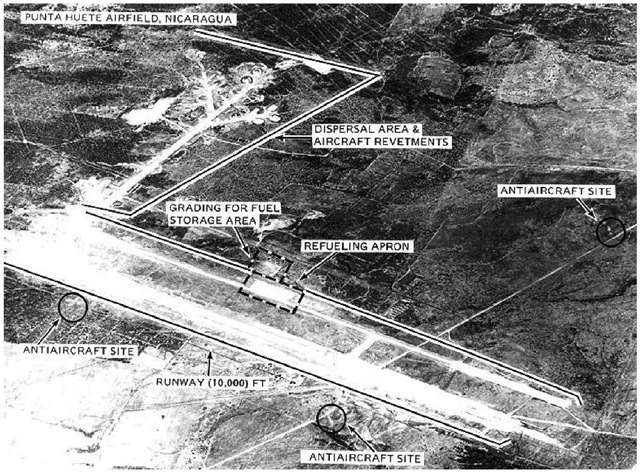
Two illustrations of AOB are given in Figs. 1.2 and 1.3. These are derived from SR-71 imagery, and show airfields in Nicaragua. Note that important elements such as the length and orientation (heading) of the runways are immediately apparent; further study shows elements of information such as the airfield defenses.
Electronic order of battle
Electronic order of battle (EOB) is really the domain of the signals-intelligence (SIGINT) community, but imagery can shed light on the topic. Things you might like to know about include defenses, such as surface-to-air missiles (SAMs) and radar installations.
Table 1.1 Air order of battle—detail.
|
Planes |
Type |
Fighter |
Weapons |
Air-to-air |
|
Air-to-ground |
||||
|
Sensors |
FLIR Radar |
|||
|
Visible |
||||
|
EW |
||||
|
Bomber |
||||
|
Tanker |
||||
|
Transport |
Civilian |
|||
|
Military |
||||
|
Trainer |
||||
|
EW |
||||
|
Reconnaissance |
||||
|
Number |
||||
|
Locations |
Bunkers |
|||
|
Runway |
||||
|
Aprons |
||||
|
Runways |
Length |
|||
|
Composition |
(Material: asphalt, dirt, concrete) |
|||
|
Direction |
||||
|
Approach |
Terrain |
|||
|
Lighting |
||||
|
Weather |
||||
|
Ground controllers |
||||
|
Logistics |
Supply lines/lines of communication |
|||
|
POL* |
Fuel Tanks |
Capacity |
||
|
Type of fuel |
||||
|
Fill factor |
||||
|
Pilots |
Number |
|||
|
Ranks |
||||
|
Training |
||||
|
Experience |
||||
|
Defenses |
Weapons |
AA guns |
||
|
AA missiles |
||||
|
Radar |
Frequency |
|||
|
Range |
||||
|
Location |
||||
|
Type |
||||
|
Locations |
FOV** |
|||
* petroleum, oil, and lubrication
** field of view
Figure 1.3 SR-71 image, Punta Huete Airfield, Nicaragua.5
For radars, the technical details are admittedly more the domain of SIGINT than imagery intelligence (IMINT), because elements of information include frequencies, pulse-repetition frequency (PRF), scan type, and pulse width and mode. Still, location and the layout of radar tell you a lot, particularly with regard to access. The size of an antenna implies characteristics such as range. You may be able to determine operational patterns. The radars’ types can be identified by comparison to known systems, e.g., air search, surface search, fire control, and target trackers. You can find out something about their networking and communications, such as nodes or types (HF, microwave, fiber, etc.). You may also be able to determine the power source.
Figure 1.4 This Quickbird image (left) shows the Sary Shagan Hen House radar, Lake Balkhash, Kazakhistan. The image was taken on July 21, 2005. These large Soviet radar (260 m long) were designed to watch for ballistic missiles, in this case from the south and southwest. For context, the April 1991 image to the right is from the NASA Space Shuttle collection, from STS039, taken with the wide-angle 40 mm lens on a Hasselblad camera. The image shows Lake Balkhash. The lake is some 350 miles long.
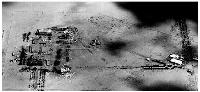
Two illustrations are given here, one of a famous Soviet Cold War system, the other of a satellite communications station. In Fig. 1.4, the orientation of the Hen House radar is associated with its primary role of watching the horizon for ballistic missiles. Given the size and orientation of the radar, and some knowledge of the wavelength used, the resolution and field of view for the radar can be determined. The satellite communications station illustrated in Fig. 1.5 provides information both for EOB and space order of battle (SOB), discussed next.
Figure 1.5 Tactical Airborne Reconnaissance Pod System (TARPS) Umm al Aysh SATCOM.
Space order of battle
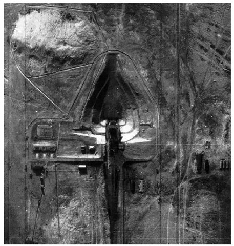
Space order of battle (SOB) is a relatively new area. It includes two components: space and ground systems. On the ground, elements of interest include launchers (boosters), launch pads and other infrastructure, and communications ground sites. Figure 1.6 illustrates the ground component with an image ofa launch pad in Baikonur.
In space, elements of information that are important are communications systems (relay satellites), operational payloads, and satellite orbital data. Figure 1.7 illustrates space control issues.
Figure 1.6 U2 image of SS-6/Sputnik Launch Pad, Baikonur.
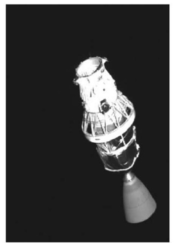
The XSS-10 satellite mission was a short-lived (about twelve hours of battery power) free-flyer deployed from a Delta II on January 29,2003, following launch from Cape Canaveral Air Force Station, Florida (the primary payload was a GPS satellite). The 28-kg satellite was an AFRL mission, flown to within 100 m of the Delta II rocket. Surrey Satellite Technology did something similar with their SNAP-1 payload, imaging the Chinese Tsinghua satellite in 2001. They also imaged the Russian Nadezha search-and-res-cue satellite, much to the surprise of the Russians.10
Naval order of battle
Naval order of battle (NOB) involves ships, of course. You want to know about battle groups: their composition (types of ships, numbers, arrangement in the group, steaming direction, velocity, etc). You want to know about ports: harbor characteristics, draft, piers, defenses, communication lines, and facilities. For ships in a harbor, you want to know their state of readiness. For individual ships, manpower, supplies, weapons, and sensors are important. In the case of carriers, you want to know about the aircraft aboard and how they are armed.
Figure 1.7 This is an image of the Delta II rocket taken in space by the XSS-10 satellite’s onboard camera. The satellite transmitted the image back to Earth shortly after separating from the booster to conduct its mission.
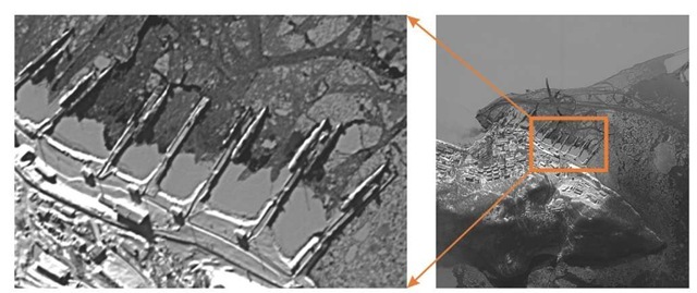
Figure 1.8 illustrates a little of what can be seen by viewing a Russian naval base. You can count the submarines and to some extent identify them, by length and shape. You get some indication of readiness by looking at the ice: are the boats locked in or is there a path to open water? Note the level of activity on the docks around the submarines. In this case, things look pretty quiet.
These illustrations for order of battle give us an idea of the types of information we would like to obtain. Next we briefly survey the various forms of remote-sensing data available historically and today. Visible, infrared, and radar imagery are illustrated.
Figure 1.8 Kamchatka Submarine Base, Russia. Located on the far-eastern frontier of Russia and the former Soviet Union, this peninsula has always been of strategic importance. Kamchatka is home to the Pacific nuclear submarine fleet, housed across Avacha Bay.
