Remote sensing systems can be divided into a handful of basic types, depending on the form of imaging technology used. These distinctions affect the resolution and sensitivity of the system, and to a certain extent, the quality of the data.
Framing systems—mostly film systems (Corona)
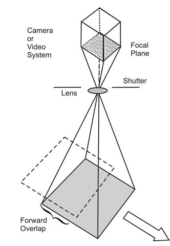
Framing systems are those that snap an image, much like a common film camera or a digital camera (still or video). An image is formed on a focal plane and stored via chemical or electronic means (film or CCD, respectively). Variations on this technique are used by some air-photo systems, and in the early Corona satellites, where the film is moved in concert with the satellite motion for longer exposure and better focus. Figure 3.29(a) illustrates such a system. The wide-field planetary camera (WFPC) on the Hubble is an example of this approach, as well as the early UoSat cameras (Fig. 1.11).
Scanning systems
Cross track (Landsat MSS, TM;AVIRIS)
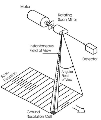
Sensors such as those on the GOES weather satellite and Landsat system consist of a small number of detectors—from one to 32 or so in the systems described later in the text. The sensor is swept from side to side, typically via an oscillating mirror, while the system flies along a track. The image is built up by the combined motion of the optic and the platform (aircraft or satellite), as shown in Fig. 3.29(b). Such sensors are called "whiskbroom" sensors.
Figure 3.29 (a) Framing system.
Figure 3.29 (b) Cross-track scanner.
Along track (SPOTHRV)
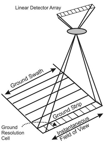
Linear detector arrays are used in systems such as the SPOT HRV sensor, the IKONOS camera, and the Quick bird sensor. The cross-track dimension is covered by the linear array, while the along-track direction is covered by the motion of the satellite. This type of sensor is termed "push broom"; Fig. 3.29(c) illustrates its use. Note how the pixels in the detector map to a line on the ground. Geometrical optics defines the map from detector pixel to the spot on the ground.
Figure 3.29(c) Push broom system.


