The science and technology of remote sensing involves the propagation of light from source to subject to sensor and relies on an understanding of the platform (or satellite bus) and the processes that transmit remotely sensed imagery to the ground. The Hubble Space Telescope serves to illustrate all these elements in the image chain.
The Hubble satellite
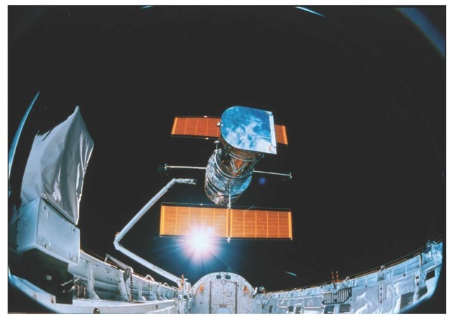
The Hubble Space Telescope (HST) was deployed April 25, 1990, from the space shuttle Discovery (STS-31). Hubble is large, with a 2.4-m diameter mirror that allows remarkable access to the distant universe, unimpeded by atmospheric absorption, scattering, and turbulence. It is useful to ponder that the 100" Hooker Telescope installed at the Mt. Wilson Observatory was the largest telescope in the world from 1917-1948. Edwin Hubble used this telescope for decades. Seven decades later, a telescope of the same size was put in orbit. From a space-operations perspective, one of the remarkable things about the satellite has been the four missions flown to date by which the space observatory was repaired and updated.
Figure 3.30 The initial deployment of the Hubble Space Telescope.
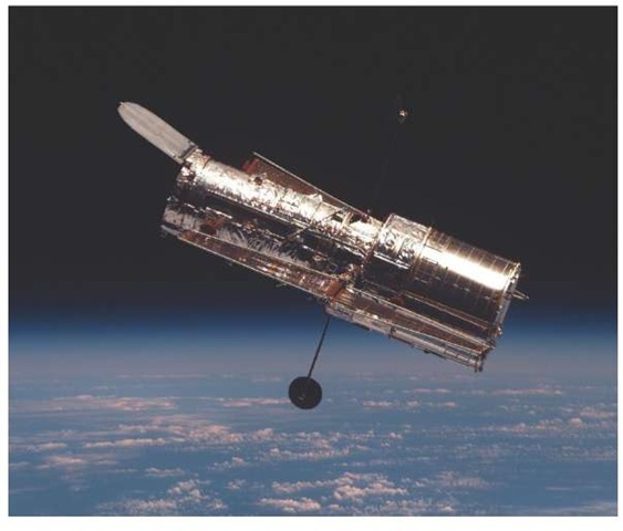
Figure 3.31 The Hubble satellite.
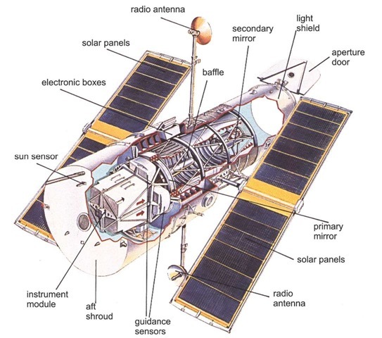
HST is roughly cylindrical, 13.1m end-to-end and 4.3 m in diameter at its widest point. The ten-ton vehicle is three-axis stabilized. Maneuvering is performed via four of six gyros, or reaction wheels. Pointing can be maintained in this mode (coarse track) or through fine-guidance sensors (FGSs) that lock onto guide stars to reduce drift and assure pointing accuracy. Hubble’s pointing accuracy is 0.007 arc sec (0.034 ^rad).
Power to the system electronics and scientific instruments is provided by two 2.4 x 12.1m solar panels, which provide a nominal total power of 5 kW. The power generated by the arrays is used by the satellite system (about 1.3 kW) and scientific instruments (1-1.5 kW), and to charge the six nickel-hydrogen batteries that power the spacecraft during the roughly 25 min/orbit in which HST is within the Earth’s shadow.22
Communications with Hubble are carried on via the Tracking and Data Relay Satellites (TDRS).Observations taken during the time when neither TDRS is visible from the spacecraft are recorded and dumped during periods of visibility. The spacecraft also supports real-time interactions with the ground system during times of TDRS visibility. The primary data link is at 1024 kbps, using the S-Band link to TDRS.23 The system routinely transfers a few GB per day to the ground station. Data are then forwarded to NASA/GSFC via landlines.
Table 3.2 Hubble Space Telescope launch and engineering characteristics.
|
Launch date/Time |
1990-04-25 at 12:33:51 UTC |
|
On-orbit dry mass |
11600.00 kg |
|
Nominal power output |
5000 W (BOL) |
|
Batteries |
Six—60 Amp-hour NiMH |
|
Orbital period |
96.66 m |
|
Inclination |
28.48° |
|
Eccentricity |
0.00172 |
|
Periapsis |
586.47 km |
|
Apoapsis |
610.44 km |
|
Science data telemetry rate |
TDRS, S-Band, SA, 1024 kbps |
|
Engineering telemetry rate |
TDRS, S-Band, MA, 32kbps |
The repair missions
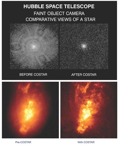
Hubble has been serviced four times; first on the STS-61 shuttle mission launched on December 2, 1993, which was the fifth flight of the Endeavour orbiter. During several days of extra-vehicular activity (EVA), the crew installed corrective optics (COSTAR) in the light path after removing the high-speed photometer (HSP) instrument, replaced the older wide-field/planetary camera (WF/PC) with a newer version (WFPC 2), and replaced malfunctioning solar arrays. The COSTAR helped correct the effects of the unfortunate spherical aberration caused by incorrect grinding of the Hubble mirror.
The next repair was made from shuttle mission STS-82, launched on February 11, 1997. The STS-82 mission again involved repairs and instrument swapping. During several days of EVA, the crew replaced a failed FGS, swapped one of the reel-to-reel tape recorders for a solid-state recorder, and exchanged the original Goddard High-Resolution Spectrograph (HRS) and the UCSD Faint Object Spectrograph (FOS) with the Space Telescope Imaging Spectrograph and the Near Infrared Camera and Multi Object Spectrometer (NICMOS).
Figure 3.32 From STS-82, the second service mission, February 19, 1997. New solar arrays have not been deployed yet (S82E5937, 07:06:57).
In addition to scheduled work, astronauts discovered that some of the insulation around the telescope’s light shield had degraded, so several thermal-insulation blankets were attached to correct the problem.
Repair mission 3A was launched December 19, 1999. During three space-walks, astronauts replaced all six Hubble gyroscopes. Four had failed, the fourth failing in November 1999, thus accelerating the launch schedule. With only two gyros, the satellite was nonoperational, and had been put in safe mode. Astronauts installed new battery-voltage regulators, a faster central computer, a fine-guidance sensor, a data recorder, and a new radio transmitter. The telescope was released from Discovery on Christmas day (5:03 p.m. CST).
Shuttle Columbia was launched for the fourth service mission on March 1, 2002 (STS-109). New rigid solar arrays, coupled with the new power-control unit, were installed, generating 27% more electrical power, an increase that roughly doubled the power available to scientific instruments (curiously, the original control algorithms designed for satellite pointing became useful for the first time.) A new camera, the Advanced Camera for Surveys (ACS), was installed.
The ACS replaced the Faint Object Camera, the last of Hubble’s original instruments. With a wider field of view and sensitivity to wavelengths ranging from ultraviolet to the far red (115-1050 nm), ACS supplanted the WFPC2 sensor as the primary survey instrument. A final service mission was scheduled for 2004, but the Columbia disaster in October 2003 has caused that mission to be significantly delayed, if not cancelled.
Operating constraints
There are two important constraints on satellite behavior, that will affect most LEO satellites.
South Atlantic anomaly
Above South America and the south Atlantic Ocean lies a lower extension of the Van Allen radiation belts called the south Atlantic anomaly (SAA). No astronomical or calibration observations are possible during spacecraft passages through the SAA because of the high background induced in the detectors. SAA passages limit the longest possible uninterrupted exposures to about twelve hours (or eight orbits). This phenomenon compromises almost all low-Earth-orbit imaging systems, though not to the same extent as astronomical systems, which depend on very low background count rates in the detector.
Spacecraft position in orbit
Because HST’s orbit is low, its atmospheric drag is significant, varying according to the orientation of the telescope and the density of the atmosphere (which depends on the level of solar activity). The chief manifestation of this effect is that it is difficult to predict where HST will be in its orbit at a given time. The position error may be as large as 30 km within two days of the last determination. This effect also impacts Earth-observing systems and can cause significant pointing errors forhigh-spa-tial-resolution systems. Systems such as Quickbird update their satellite ephemeris information once an orbit.
The telescope itself
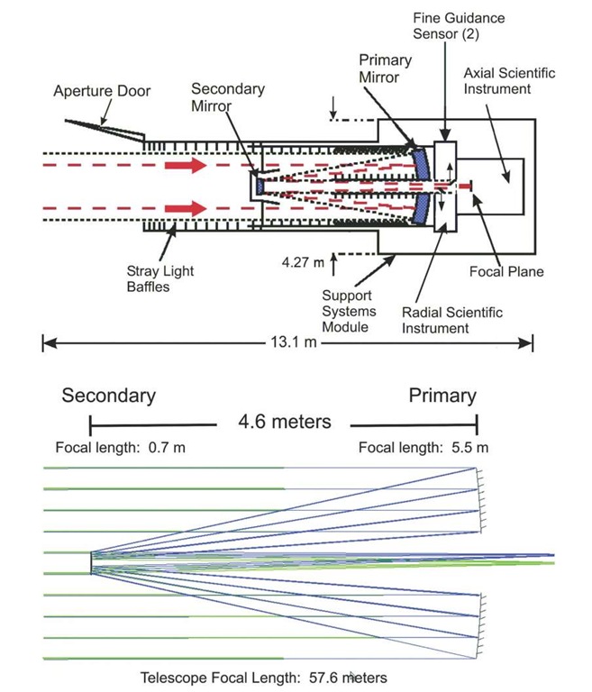
The Hubble is an f/24 Ritchey-Chretien Cassegrain system with a 2.4-m-diameter primary mirror and a 0.3 m secondary mirror. The Cassegrain design for the Hubble is very common among satellite systems. The primary mirror is constructed of ultra-low-expansion silica glass and coated with a thin layer of pure aluminum to reflect visible light. A thinner layer of magnesium fluoride is laid over the aluminum to prevent oxidation and reflect ultraviolet light. The secondary mirror is constructed from Zerodur, a very-low-thermal-expansion (optical) ceramic. The effective focal length is 57.6 m. Figure 3.33 illustrates the optical design for the telescope. The distance between the mirrors is 4.6 m, and the focal plane is 1.5 m from the front of the primary mirror. The angular resolution at 500 nm is 0.043 arc sec (0.21 |rad). The fine guidance sensors (FGS) view through the primary optic. The off-axis viewing geometry does not interfere with imaging, and allows use of the large primary optic for the necessary detector resolution.
Figure 3.33 Hubble optics. The mirrors are hyperboloids, the secondary is convex. The primary has a focal length of 5.5 m and a radius of curvature of 11.042 m. The secondary has a focal length of-0.7 m and a radius of curvature of 1.358 m. The bottom image is an accurate ray trace for the Cassegrain telescope.
Note that a requirement for the spacecraft was a pointing accuracy (jitter) of 0.007 arc sec. This was more easily achieved after the first set of solar arrays was replaced. The flexible array design vibrated rather badly every time the satellite moved from sun to shadow, or shadow to sun—that is, twice an orbit. This design error required redesign of the satellite pointing control algorithms.
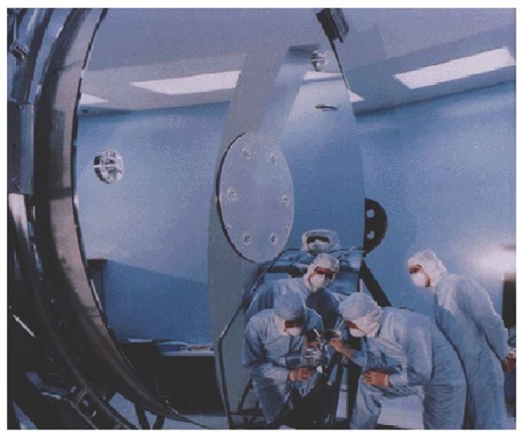
Figure 3.34 The primary mirror of the Hubble telescope measures 2.4 m (8 ft) in diameter and weighs about 826 kg (1820 lbs). By comparison, the Mt. Wilson 100 inch solid glass mirror weighs some 9000 pounds.25 The center hole in the primary mirror has a diameter of 0.6 m.
It was soon found that there was a more serious problem with the Hubble: the mirror was not ground to quite the right prescription, and it suffered from spherical aberration (too flat by about 4 ^m at the edges.) As a consequence, new optics designs were created, and a corrective optic was added for the existing instruments (COSTAR). Subsequent scientific instruments, such as the WFPC2, built corrections into the optics.
Detectors—Wide Field and Planetary Camera
The Hubble normally carries four or five distinct sensors. The Wide Field and Planetary Camera 2 (WFPC2) is described below. Hubble’s scientific instruments are mounted in bays behind the primary mirror. The WFPC2 occupies one of the radial bays, with an attached 45° pickoff mirror that allows it to receive the on-axis beam. (The best image quality is obtained on-axis.)
Figure 3.35 Top Left: A Faint Object Camera (FOC) image of a star taken prior to the STS-61 shuttle mission to service the HST, during which astronauts installed COSTAR. The broad halo (one-arc sec diameter) around the star is caused by scattered, unfocused starlight. Top Right: Following installation, deployment, and alignment of COSTAR, starlight is concentrated into a 0.1-arc sec diameter circle, STSci-PRC1994-08; Bottom Left: The central region of the Active Galaxy NGC 1068, FOC pre-COSTAR. Bottom Right: NGC 1068, with COSTAR, early January, 1994, at a distance of 60 million light years. STSci-PRC1994-07.
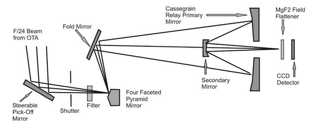
Figure 3.36 WFPC2 optics. Light enters the optical train from the main telescope at left.
The WFPC2 field-of-view is distributed over four cameras by a four-faceted pyramid mirror near the HST focal plane. Each of the cameras contains an 800 x 800 pixel Loral CCD detector. Three wide-field cameras operate atf/12.9, and each 15-^m pixel images a 0.10 arc sec portion of the sky. The three wide-field cameras cover an L-shaped field of view of 2.5 x 2.5 arc min. The fourth camera operates at 0.046" (0.22 ^rad) per pixel f/28.3) and is referred to as the planetary camera. This sensor is therefore operating at the full resolution of the telescope. The fourth camera observes a smaller sky quadrant: a 34" x 34" field (note that 34" is 34 arc sec, not 34 inches.) This is a sufficiently large field of view to image all the planets but Jupiter. The spectral range lies from approximately 1150A to 10,500A. Exposure times range from 0.11 to 3000 seconds.
Example: Diffraction and resolution limits
Rayleigh criteria
The angular resolution for the telescope is given as 0.043" (arc sec), with the slightly larger value of 0.046" for the combined Hubble/WFPC2 system. These values include all the effects that are ignored in the simplest approximation to the Rayleigh criteria,![]() diameter. A few numbers are tested here, assuming a deep blue wavelength (410 nm):
diameter. A few numbers are tested here, assuming a deep blue wavelength (410 nm):
Compare this to the given value
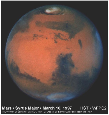
Figure 3.37 This image of Mars was taken with the WFPC2 on March 10, 1997, just before Mars opposition, when the red planet made one of its closest passes to Earth (about 100 million km). At this distance, a single picture element (pixel) in WFPC2′s planetary camera spans 22 km on the Martian surface. The image is less than 335 pixels across—the Martian diameter is 6794 km. This picture was created by combining images taken with blue (433 nm), green (554 nm), and red (763 nm) filters. Credit: STScI-PRC97-09, March 20,1997, David Crisp (JPL) and the WFPC2 Science Team.
Applying this value to the hypothetical problem of the ground resolution that Hubble would have if pointed down, we get:
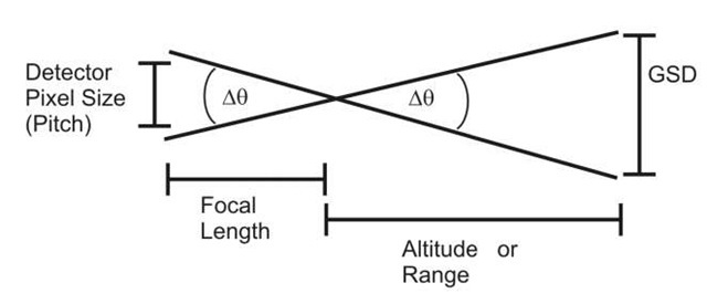
Figure 3.38 For the Hubble/WFPC2 combination, altitude is 600 km, detector size is 15 ^m, and focal length is 57 m.
If Hubble were pointed downward, you would get a GSD of 12 cm. The calculations can be repeated for 0.046 arc sec, but the increase is only a few percent.
Geometric resolution
The above implies that the detector has infinite resolution. In reality, however, it does not. Using the concept of similar triangles shown previously and the values for the detector’s pixel size, given above, we can compare detector resolution to the best resolution offered by the telescope:
which is slightly worse than the best the telescope can do—the airy disk from a distant star, or a small bright light on the ground, would not quite fill one detector pixel. The detector is under sampling the image.
