Queue
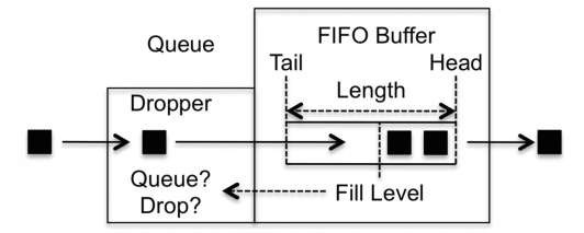
A queue contains two sub-blocks: a buffer and a dropper. The buffer is where packets are stored while awaiting transmission. It works in a FIFO (first in, first out) fashion, which means that the order in which packets enter the buffer is the same in which they leave. No overtaking occurs inside the buffer. The main parameter that defines the buffer is its length, which is how many packets it is able to store. If the buffer is full, all newly arrived packets are discarded.
For ease of understanding throughout this topic, we always consider the situation where packets are placed in queues. However, this is not always the case. In certain queuing schemes, what is placed in the queue is in fact a notification cell, which represents the packet contents inside the router.
The decision whether a packet should be placed in the queue buffer or dropped is taken by the other queue block, the dropper. The dropper has one input, which is the queue fill level. Its output is a decision either to place the packet in the queue or to drop it. The dropper works in an adaptive control fashion, in which the decision to either place the packet in the queue or drop it is taken according to the queue fill level. So as the queue fills up or empties, the dropper behaves differently.
As a QOS tool, the queue has one input, which is the packets entering the queue, and one output, which is the packets leaving the queue, as illustrated in Figure 2.8.
When a packet enters a queue, it first crosses the dropper block, which, based on the queue fill level, makes a decision regarding whether the packet should be placed in the FIFO buffer or discarded. If the packet is placed in the buffer, it stays there until it is transmitted. The action of moving a packet out of the queue is the responsibility of the next QOS tool we discuss, the scheduler.
Figure 2.8 The queue operation
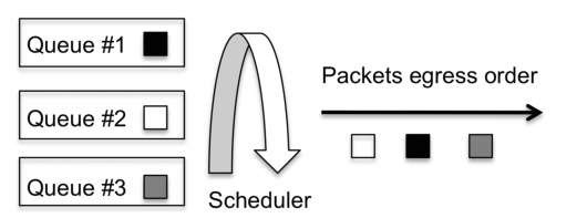
Figure 2.9 The scheduler operation
If the queue is full, the decision made by the dropper block is always to drop the packet. The most basic dropper is called the tail drop. Its basic behavior is that, when the queue fill level is less than 100%, all packets are accepted, and once the fill level reaches 100%, all packets are dropped. However, more complex dropper behaviors can be implemented that allow the dropping of packets before the queue buffer fill level reaches 100%.
The Scheduler
The scheduler implements a multiplexing operation, placing N inputs into a single output. The inputs are the queues containing packets to be serviced, and the output is a single packet at a time leaving the scheduler. The scheduler services a queue by removing packets from it.
The decision regarding the order in which the multiple queues are serviced is the responsibility of the scheduler. Servicing possibilities range from fair and even treatment, to treating some queues as being privileged in terms of having packets be processed at a faster rate or before other queues.
The scheduler operation is illustrated in Figure 2.9 , which shows three queues, each containing a packet waiting for transmission. The scheduler’s task is to decide the order in which queues are serviced. In Figure 2.9, queue 3 is serviced first, then queue 1, and finally queue 2. This servicing order implies that the egress order of the packets is the gray packet first, then the black packet, and finally the white packet. Figure 2.9 provides
just a simple scheduler example. In reality, there are multiple possible schemes regarding how the scheduler decides how to service the queues.
In some ways, the scheduler operation is the star of the QOS realm. It is the tool by which the QOS principle of favoring some by penalizing others becomes crystal clear. We shall see in detail that if traffic is split into classes of service and each class is mapped into a specific queue, the scheduler provides a very clear and precise method to decide which traffic is favored by being effectively prioritized and transmitted more often.
The Rewrite Tool
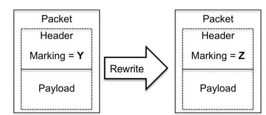
The rewrite tool allows a packet’s internal QOS marking (simply called its marking), to be changed. The exact location of the marking depends on the packet type, for example, whether it is an IP or MPLS packet, but for now simply assume that there is a marking inside the packet.
The rewrite tool has one input and one output. The input is a packet that arrives with a certain marking, and the output is the packet with the "new" marking, as illustrated in Figure 2.10.
Two major scenarios require application of the rewrite tool. In the first, this tool is used to signal information to the next downstream router. The second scenario is when the packet marking is considered untrustworthy. In this case, the router at the edge of the network can rewrite the marking to ensure that the other network routers are not fooled by any untrustworthy marking in the packet.
We mentioned the lack of signaling between neighbors or end to end, and raised the question of how to signal information between routers. Figure 2.11 illustrates this challenge with a practical example in which two packets, numbered 1 and 2, both with a marking of X, cross Router A and are both classified into the class of service COS1. However, packet 1 is colored green and packet 2 yellow. At the other end, Router B has a classifier that inspects the packets’ QOS markings to decide to which class of service they belong.
Figure 2.10 The rewrite operation
Figure 2.11 Information propagation
Figure 2.12 Rewrite tool applicability
If Router A wants to signal to Router B that the packets belong to the same class of service but they are colored differently, it has only one option because of the lack of signaling, which is to play with the packet-marking parameters used by Router B’s classification process. For example, if Router A applies the rewrite tool to the second packet and changes its marking from X to Y, Router B’s classifier can differentiate between the two packets, as illustrated in Figure 2.12.
However, Router A cannot control the classification rules that Router B uses because of the lack of signaling. So the success of the rewriting scheme always depends on the Router B classifier configuration being coherent so that the marking of X is translated into COS1 and color green and the marking of Y is also translated into COS1 but retains the color yellow. Consistency is crucial.
Example of Combining Tools
Now that we have presented each tool separately, we combine them all in this section in a simple walkthrough example to illustrate how they can be used together on a router. However, this should be seen as just an example that glues all the tools together. It is not a recommendation for how to combine QOS tools, nor of the order in which to combine them.
In fact, the sole input to the decision regarding which tools to use and the order in which to use them is the behavior that is required to be implemented. To this end, our example starts by presenting the network topology and defining the desired behavior. Then we discuss how to combine the tools to match the defined requirements.
Figure 2.13 Traffic flow across the router
Table 2.1 PHB requirements
The example topology is the simple scenario illustrated in Figure 2.13. A router with one ingress and one egress interface is receiving black and white traffic. The differentiating factor between the two types of packets is the markings they carry. Hence, the markings are the parameter used by the classifier. The PHB requirements to be implemented are summarized in Table 2.1.
Starting with the classification requirements, black packets should be placed in the class of service COS1 and white packets in COS2. Both types of traffic are metered and policed to implement the coloring requirements listed in Table 2.1. In terms of the queuing and scheduling requirements, black packets should be placed in queue 1 (Q1), which has a higher priority on egress, and white packets are placed in queue 2 (Q2). The rate of traffic leaving the router should not exceed 8 megabits per second (8 Mbps), but the rate control should also ensure that excess traffic is stored whenever possible rather than being discarded.
The final requirement regards the rewrite rules. White packets colored yellow should have their marking set to the value X before leaving the router, to signal this coloring scheme to the next downstream router.
These requirements are all the necessary details regarding the PHB. Let us now combine the QOS tools previously presented to achieve this PHB, as illustrated in Figure 2.14. In Figure 2.14, only three white and three black packets are considered for ease of understanding.
The first step is classification, to inspect the packets’ markings and identify the traffic. Black traffic is mapped to the class of service COS1 and white traffic to the class of service COS2.
Figure 2.14 Tools combination scenario
From this point onwards the traffic is identified, meaning that the behavior of all the remaining tools towards a specific packet is a function of the class of service assigned by the classifier.
The metering and policing tools are the next to be applied. The metering tool colors each packet according to the input arrival rate. The result is that for both the white and black traffic types, one packet is marked green, one marked yellow, and the third marked red. As per the defined requirements, the policer drops the red packet and transmits all the others. The result is that black packet 3 and white packet 3 are discarded.
Now moving to the egress interface, packets are placed into the egress queues, with black packets going to queue 1 and white packets to queue 2. We assume that because of the current queue fill levels, the dropper associated with each queue allows the packets to be put into the queues. The requirements state that the scheduler should prioritize queue 1. As such, the scheduler first transmits packets in queue 1 (these are black packets 1 and 2), and only after queue 1 is empty does it transmit the packets present in queue 2 (white packets 1 and 2). This transmission scheme clearly represents an uneven division of resources applied by the QOS tool to comply with the requirement of prioritizing black traffic.
The shaper block then imposes the desired outbound transmission rate, and when possible, excess traffic is stored inside the shaper.
The last block applied is the rewrite tool, which implements the last remaining requirement that white packets colored yellow should have their marking rewritten to the value X. The rewrite block is usually applied last (but this is not mandatory), following the logic that spending cycles to rewrite the packets markings should occur only once they have passed through other QOS tools that can drop them, such as the policer.
The behavior described above takes place inside one router. Let us make the example more interesting by adding a downstream neighbor (called Router N) that maintains the same set of requirements listed in Table 2.1. For ease of understanding, we again assume that only white and black traffic is present, as illustrated in Figure 2.15.
What set of tools should Router N implement to achieve consistency? The same?
Figure 2.15 Adding a downstream neighbor
Figure 2.16 Bidirectional traffic
The PHB concept implies that once packets leave a router, all the previously classification is effectively lost, so the first mandatory step for Router N to take is to classify traffic. It should not only differentiate between white and black packets, but should also take into account that packets with a marking of X represent white packets that were colored yellow by its neighbor. Otherwise, having the upstream router use the rewrite tool becomes pointless.
Regarding metering and policing, if the rates defined in Table 2.1 have been imposed by the upstream router, Router N does not need to apply such tools. However, this decision touches the topic of trust relationships. If Router N cannot trust its neighbor to impose the desired rates, it must apply tools to enforce them itself.
Regarding queuing and scheduling, it is mandatory for Router N to implement the scheme described previously, because this is the only possible way to ensure that the requirement of prioritizing black traffic is applied consistently across all the routers that the traffic crosses.
Let us now remove Router N from the equation and replace it by adding bidirectional traffic, as illustrated in Figure 2.16 . Achieving the set of requirements shown in Table 2.1 for the bidirectional traffic in Figure 2.16 is just a question of replicating tools. For example, all the tools we presented previously are applied to Interface A, but some, such as metering and policing, are applied only to traffic entering the interface (ingress from the router’s perspective), and others, such as shaping, queuing, and scheduling, are applied only to traffic leaving the interface (egress from the router’s perspective).
This is a key point to remember, QOS tools are always applied with a sense of directionality, so if, for example, it is required to police both the traffic that enters and leaves an interface, effectively what is applied is one policer in the ingress direction and another policer in the egress direction.
Any QOS tool can be applied at the ingress or egress; the impetus for such decisions is always the desired behavior. This example uses policing as an ingress tool and shaping as an egress tool.The only exception is the classifier tool. Because the PHB concept implies that any classification done by a router is effectively lost once traffic leaves the router towards its next downstream neighbor, applying it on egress is pointless.
This simple example is drawn from a basic set of requirements. Parts Two and Three of this topic show examples of using these tools to achieve greater levels of complexity and granularity.


