Traffic on 3G Networks
Voice traffic on a 3G network continues to be circuit switched, so in this sense it is identical to voice traffic on a 2G network. The difference lies in the data service packets, which are routed in a packet-based network structure. As we have discussed, an end user packet is not processed as a native IP packet until it reaches the GGSN. IP traffic between the SSGN and the GGSN travels in a GTP tunnel over the Gn interface or, in a roaming situation, over the Gp interface so the user can be routed over another operator’s network to their home GGSN.
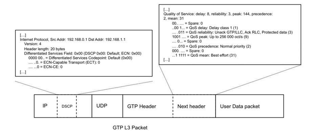
From a QOS perspective, this mobile traffic is clearly handled as a best-effort service, because it is transported through a tunnel and because traffic in a GPRS network is generally placed in a best-effort class of service. Examples of GPRS network traffic include UDP-based name queries and lookup and TCP-based HTTP downloads. Another common traffic type is webcasting traffic, described in topic,which gives the impression of being a real-time service when, in fact, it is just a streamed file that is being downloaded. QOS could be used here to map the radio QOS classes to the GTP header and appropriate DSCP class in the IP header for the GTP packet, but in 3G and GPRS network this is more theoretical rather than an actual implemented service. Figure 10.8 shows a GTP packet and delineates the QOS extension header from the DSCP part of the IP packet.
GPRS traffic flows in a hub-and-spoke pattern because each subscriber is assigned to a home GGSN. This "all roads lead to Rome" traffic pattern means that the subscriber always enters and exits the network through the same GGSN regardless of whether the user is at home or is traveling.
Figure 10.8 GTP QOS versus IP QOS
The SSGN connected to the RNC performs a lookup of the subscriber by querying the HLR. If the subscriber is on their home GGSN, the SSGN routes the traffic to its destination. If the subscriber is roaming, the SSGN routes the traffic to their home GGSN. The result is the creation of GTP tunnels on the Gn or Gp interface in a GPRS network. Clearly, it is as hard to manage QOS functions across operators in roaming situations as it is to maintain QOS in Internet for packets that traverse service provider boundaries.
In summary, it is possible to implement IP QOS solutions in GPRS networks, but in most cases no transparent QOS mappings between radio and IP traffic are implemented for GPRS traffic passing over the mobile backhaul on the Gn or Gp interface between the SSGN and the GGSN. The most common approach is to implement a QOS mapping on the GGSN when the packets leave the mobile network, creating a mapping between the 3GPP and other IP QOS classes such as DiffServ and IP DSCP.
LTE Network Components
3GPP, or LTE, is the next evolutionary step in radio networks. (Note that LTE and 4G are synonyms.) With LTE, the radio interface is not redirected to a PSTN network, but is instead IP based. Voice is seen like any other application in an LTE network.
As an aside, LTE networks can be data-only networks that mix 3G and LTE traffic. On these networks, only the data is handled as LTE traffic, while the voice traffic remains as GSM/CDMA. Also, there are a number of variations of the voice traffic. For example, the 3GPP voice solution is generally -MS (-P Multimedia System- . Discussing all the possibilities is beyond the scope of this topic.
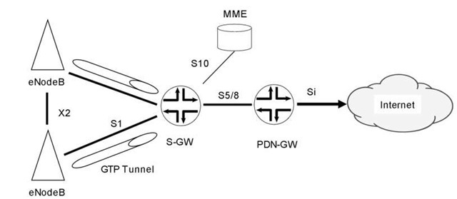
Compared to a GPRS network, the LTE network is flat. LTE has no radio control node like an RNC that collapses and aggregates the traffic. The LTE NodeB, sometimes also called the eNodeB, connects directly to an IP network, towards the S- GW (Serving Gateway), MME ( Mobility Management Entity ), and PDN – GW ( Packet Data Network Gateway). The MME handles signaling, while the S-GW and PDN-GW handle the actual termination of tunnels and forwarding of traffic (we discuss these later).
The S-GW is the anchor point for the termination of mobile users in the packet network. It is the end point for the GTP tunnel between eNodeB and manages roaming to other networks.
The PDN-GW, or just P-GW, is the gateway between the LTE network and other networks. It acts very much like GGSN with regards to managing how it forwards users to either the Internet or to a private VPN. The PDN- GW also manages the IP addressing for the end users. Note that the S-GW and PDN-GW functions can be on the same node, which often makes more sense than splitting them. Other network functions can also be running on the PDN- GW, such as NAT to map IPv6 addresses to IPv4 addresses.
Figure 10.9 LTE architecture
The MME provides the control-plane function for LTE. It is responsible for authentication and management.
SAE (System Architecture Evolution), as the LTE core network architecture is called, is an all-IP network that includes both mobile backhaul and RAN. The main components of the SAE architecture are the Evolved Packet Core (EPC), MME, S-GW, and PDN – GW.
The LTE interface names change, of course, from GPRS. Figure 10.9 illustrates the LTE S1 and Si interfaces, which are equivalent to the GPRS Gn and Gi interfaces, respectively. Figure 10.9 also separates the S-GW and PDN-GW functions to explain the interface naming simply. However, as stated earlier, the S-GW and PDN-GW can be on the same device.
One major difference between LTE and 3G, apart from the network topology, is that LTE is all IP. So, for instance, the voice is handled as VoIP. This means that all LTE operators run an IP transport network, starting from the eNodeB. The GTP tunnel between the eNodeB and the S- GW is more for administrative purposes, such as tracking and controlling users. Also, there is only one tunnel between the eNodeB and the S- GW, unlike the several tunnels present with GPRS. The TEID information differentiates the users in the GTP tunnel.
The S1 and X2 interfaces shown in Figure 10.9 are considered to be RAN interfaces. These interfaces are transported over the IP RAN as a part of the mobile backhaul network, possibly using public networks, such as E-line or E-LAN. These networks are not considered secure enough to transport unencrypted data. The security is provided by IPsec, whose use is mandatory to protect the integrity for the traffic.
-Psec tunnels carry encapsulated voice and data traffic, plus signaling, between the eNodeB and the MME. The requirement for IPsec tunnel and key management is defined in the 3GPP documents TS 33.210 [2] and TS 33.31, which discuss the Layer 3 security and authentication framework. These documents require that IPsec ESP conform to RFC 4303 [3] to support integrity and replay protection, and that certificate authentication be done by IKEv2.
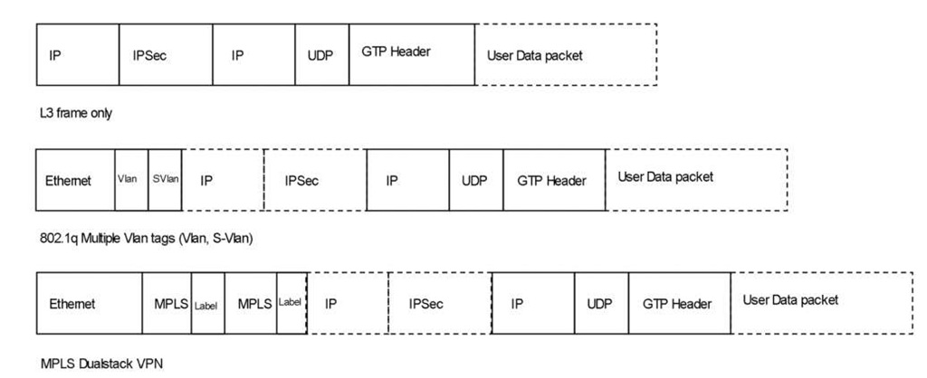
Figure 10.10 Encapsulations of LTE packets sent between NodeB and S-GW
The 3GPP mandates that IPsec be implemented on the eNodeB, and the two specifications mentioned above detail the IPSec implementation requirements. IPSec must be supported, but deploying it is not mandatory. After performing a risk assessment, the operator must decide whether to use IPSec.
However, the IPsec requirements are currently the subject of much debate. One current question is whether IPsec is necessary if the operator manages the network, end to end, from the eNodeB to the S-GW. Another question is whether IPsec is mandatory just because no authentication or encryption exists, by default, for voice traffic on an LTE network.
The extensive usage of IPsec makes traffic paths and QOS a tough challenge. In the case of a centralized S-GW using IPsec, x2 to x2 traffic termination might result in a slow or difficult handover for roaming mobile users.
While the design of LTE networks is beyond the scope of this topic, it needs to be mentioned that LTE networks have a significant overhead because of the security information (based on the IPsec header) and because of the control and user tracking (based on the GTP header) of traffic between the eNodeB and the S-GW. To scale and segment, the network probably needs to be provisioned similarly to large access and distribution metro networks, with extensive usage of VLANs and MPLS stack labels to scale the provisioning of the eNodeB. Figure 10.10 shows the header overhead involved. The first packet is Layer 3 only, the second is for Ethernet aggregation using VLAN/S-VLAN, and the third shows the MPLS dual stack that is used with MPLS VPN technologies, such as L3VPN, VPLS, and pseudowires.
LTE Traffic Types
LTE networks have more traffic types than 3G networks, because all traffic is transported natively as IP packets. GTP tunneling exists, but all services and thus traffic runs over the IP network. LTE traffic types can be divided into two groups: control plane and signaling, and user traffic.
On LTE networks, a vast amount of signaling and control plane traffic passes through the IP network compared with the packet-based network portion of 3G networks. Control plane and signaling traffic can be direct, indirect, or something in between.
An example of a direct control plane and signaling protocols is the mobile signaling SCTP (Stream Control Transmission Protocol), which is used to encapsulate signaling between eNodeB and MME across the NAS (Non-Access Stratum).
Indirect control plane and signaling protocols are related to the devices in the packet-based transport layer. They include the Layer 2 protocols such as ARP, spanning tree, and other resiliency protocols. Other examples are the Ethernet OAM protocols, which are used when the dominant media type is Ethernet. Examples of Ethernet OAM protocols are IEEE 802.3ah (Link OAM) and IEEE 802.1ag (Connectivity Fault Management). The indirect control plane and signaling protocols also include the traditional Layer 3 protocols such as the IGPs (ISIS and OSPF), BGP, and MPLS, as well as link-local protocols, such as VRRP and PIM.
One example of both direct and indirect control plane and signaling traffic is time signaling. In 3G networks, time synchronization is built into the transport media, for example, TDM serial links or ATM networks. Unlike TDM and cell- based networks, Ethernet carries no synchronization information in its media. When the IP RAN and mobile backhaul network is upgraded to Ethernet, the base stations are isolated from the synchronization information that used to be carried over the TDM. With LTE, voice packets in need of time and clock synchronization pass in the very same IP network in the IP RAN and mobile backhaul as data traffic, for example, HTTP traffic. The classic time service synchronization is provided by either the NTP protocol, IEEE 1588, or Synchronous Ethernet as a part of power over Ethernet (IEEE 802.3af).
LTE user traffic consists of both voice and Internet applications running over TCP and UDP. Traffic is both unicast and multicast, the latter including videoconferencing and online streaming media. One point to mention is that voice is just user data-plane traffic for the LTE network. An example is SIP. A VoIP packet that uses SIP for call setup is still data, just as when the call is established with UDP packets with an RTP header.
LTE Traffic Classes
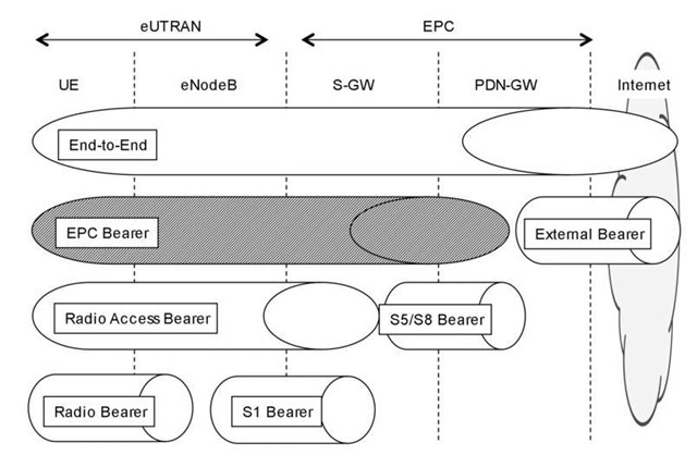
A GRPS session is referred to as a PDP context. In LTE, the equivalent is generally called the bearer, which reflects a context or session. LTE networks can have several bearers, which are used at different stages along a path in the LTE network. Figure 10.11 shows the relation between the bearer services.
The LTE network is divided into different areas, with new names, including eUTRAN (evolved UMTS Terrestrial Radio Access Network), which reflects the radio-only part, and EPC (Evolved Packet Core), which handles the packet-based networks.
Figure 10.11 Bearer services
A session that starts from the User Equipment (UE) and traverses the RAN and mobile backhaul towards S-GW/PDN-GW forms an EPC bearer. The focus of this discussion is on the EPC bearer, not on the end-to-end bearer, because the external barrier that is a part of the end-to-end bearer might go over the Internet, crossing AS boundaries, so it needs to interact with other QOS policy domains. The assumption is that the EPC bearer runs within the same operator entity and thus within a single managed network.
Before trying to map the 3GPP and IETF QOS functions and classes for the EPC Bearer, let us look at the specifics of 3GPP QOS. We briefly examine traffic separation, the types and numbers of traffic classes needed, and the QOS classes of service needed for radio traffic.
The 3GPP has defined QOS aspects in several specifications. One of the original documents, TS 23.107, "QoS Concept and Architecture," describes a framework for QOS within UMTS. This specification defines the four traffic classes shown in Figure 10.12.
The 3GPP TS 23.203 [4] and TS 23.207 [5] specifications go further, introducing QCI (QOS Class Identifier) and nine classes for LTE. QCI is an identifier that controls the QOS details on the eNodeB, and it divides the bearers into two groups: GBR (Guaranteed Bit Rate) bearers and non- GBR bearers. Figure 10.13 describes the nine QCI groups. Figure 10.13 shows that some of the services are backward- compatible between the UMTS and LTE specifications.
Note that the 3GPP QOS models can be adapted by the IntServ and DiffServ model. This topic focuses on the DiffServ and PHP QOS models; the IntServ QOS model is beyond the scope of this topic.
|
Traffic class |
Fundamental characteristics |
Example of the application |
|
Conversational Real-time |
- Preserve time relation (variation) between information entities of the stream. Conversational pattern (stringent and low delay ) |
-Voice (VoIP) |
|
Streaming Real-time |
- Preserve time relation (variation) between information entities of the stream |
- Streaming video |
|
Interactive best-effort |
- Request response pattern - Preserve payload content |
- Web browsing |
|
Background best-effort |
- Destination is not expecting the data within a certain time - Preserve payload content |
-Background downloads, non realtime |
Figure 10.12 UMTS traffic classes in TS 23.107
Figure 10.13 LTE traffic classes in TS 23.203 [4]
For packet network designers, the ratio of over-provisioning is a key topic of interest, but for radio network designers, the key topic is quality of service. IP RAN and QOS designs need to satisfy both world-views simultaneously. The micro versus macro angle is very much in the spotlight here regarding how to achieve quality for the service while at same time offering a good business model. The macro model very much adapts to GBR, while the micro model is non-GBR The GBR model can be translated to the EF class in the IETF DiffServ model, using high priority and weight and buffer tuning to achieve absolute service.
Returning to the LTE QOS and the EUTRAN and EPC, one question is whether four to nine classes in radio QOS can be mapped to the classic packet- based well – known classes following the IETF DiffServ model. If we step back from academic solutions and demands to a practical approach, we see that LTE has four classes and two or three priority levels, a number that is very similar to the well-known QOS classes in today’s packet-based networks: Network-control (NC), Expedited-forwarding (EF), Assured-forwarding (AF) and Best-effort (BE).
Control and signaling, and voice are two classes (NC and EF) that can be grouped into the same priority. These two traffic types cannot be over-provisioned or dropped. Instead, they require guaranteed delivery to achieve the desired quality level. Traffic volume estimates for voice on LTE networks are similar VoIP and SIP.For example, if each SIP call requires 80 kbps in one direction, the estimated number of VoIP sessions needs to fall within these bandwidth and delay demands.
The bulk of traffic, that is, the TCP traffic, is in the best-effort class (BE). Surfing the web, email, chat, and so forth, are all classic best-effort applications. With mobile networks, handheld TVs and video clips are two interactive services that are driving the increased bandwidth demands and that are used to justify GGSN and LTE capabilities. However, streamed compressed media content in unicast format and long-lasting sessions.Instead, they are long-lasting TCP sessions used to download and watch compressed video content. Neither is very different from ordinary web service usage, and they can be managed well with TCP mechanisms. In practice, there are no differences between buffered and background TCP content if we speak in terms of QCI classes.
One of the real challenges is handling true broadcasting, in the form of real- t ime, multicast streaming media. An example of one such application is video conferencing.It is loss sensitive, but to some extent can handle delay that results from local playback and buffering. QOS for online broadcasting is probably one of the biggest challenges for mobile solutions.
|
IETF Class |
3GPP Class |
Priority |
Weight |
Buffer |
Traffic types |
|
Network-Control (NC) |
5/ Conversational |
High |
10% |
10% |
Network control traffic |
|
Expedited-Forward (EF) |
1/ Conversational |
Strict High |
25% |
25% (alt x ms of traffic) |
Voice and Voice signaling |
|
Assured-Forwarding (AF) |
2/3/7 Streaming |
Medium/Low |
50% |
50% |
Streaming bigger packets |
|
Best-effort (BE) |
All others |
Low |
25% |
25% |
TCP and Buffered data |
Figure 10.14 Example of mapping traffic classes between the IETF and 3GPP
Figure 10.15 Example of traffic class mapping IETF<->3GPP
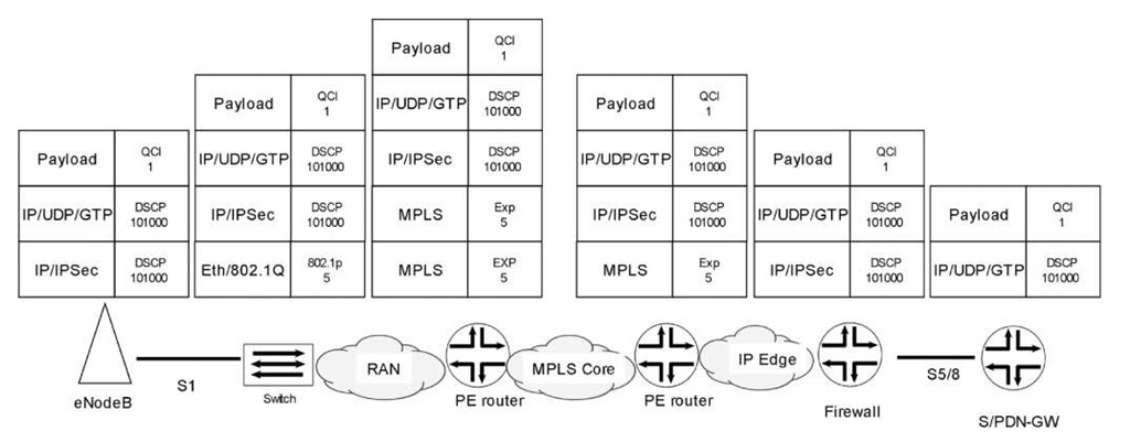
Figure 10.14 shows an example of mapping traffic classes in an LTE/UTRAN network between radio and packet QOS.
Let us follow a packet between eNodeB and S-GW/PDN-GW. Figure 10.15 shows the QOS PHB changes to this packet. Many media and headers can be involved, including DSCP, 802.1p, and MPLS EXP.
![LTE traffic classes in TS 23.203 [4] LTE traffic classes in TS 23.203 [4]](http://what-when-how.com/wp-content/uploads/2012/02/tmpC189_thumb2_thumb.jpg)
