Radio Access Networks (RANs) connect mobile base stations to the mobile backhaul network. RAN networks have evolved from 2G networks with GSM handsets to 3G, which introduces IP. However, 3G networks do not offer true IP-based service. Rather, SSGN tunnels the data portion of the traffic to GPRS routers, which act as gateways to IP-based networks. The next phase, 4G networks, commonly called Long-Term Evolution (LTE), introduces more IP into mobile backhaul networks, transforming RAN networks into IP RAN networks. In LTE networks, voice packets are encapsulated into IP packets and are transmitted over IP RAN, not over the legacy PSTN network as is the case with 3G.
This case study examines the recently evolved LTE network, with a focus on packet-based QOS. It starts by discussing the components of 2G and 3G networks, how traffic is carried on these networks, and how they have evolved to LTE. The case study then describes the LTE network components and traffic, and offers guidelines and suggestions for using QOS.
Before starting, we should note that currently, only a limited number of LTE networks have been installed, and they are only small-scale implementations operating in a trial or test mode. So if we ask whether QOS been successfully designed, verified, and implemented in these islands of LTE networks, the answer is, of course not. To reflect this reality, this topic does not deliver truths gained from long experience and written in stone, but rather examines the mapping between radio-based and packet-based QOS in these early LTE networks.
Evolution from 2G to 4G
This topic focuses on QOS in packet-based networks, and this topic presents a QOS case study for IP-based RAN as a part of a mobile backhaul network. However, a brief introduction of 3G network evolution to 4G and LTE is necessary to describe the fundamental changes that occur with LTE and the packet transport for this service. We must discuss some basic mobile functions and features before explaining the QOS scenario for IP RAN and mobile backhaul. This discussion touches on the packet-handling services in 3G and 4G networks. GSM (Global System for Mobile Communications), CDMA (Code Division Multiple Access), and any other pure mobile voice and signaling architectures are described only briefly. Also, the 3GPP evolution is covered only in generic terms.
2G Network Components
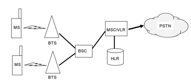
Second Generation (2G) mobile networks and GSM are synonymous, but GSM is widely seen as one of the key components within 2G mobile phone systems. With GSM, both signaling and speech channels are digital. This facilitates the widespread implementation of data communication applications into the mobile network. GSM is a cellular network, which means that mobile phones connect to it by searching for cells in the immediate area. A cell is a part of a base station, and several base stations form the cellular network. GSM networks operate in a number of different carrier frequencies bands, normally within the 900- MHz or 1800- MHz band, although this varies from country to country. The frequencies are divided into time slots. The elements in a GSM mobile network can be seen in Figure 10.1.
The MS (Mobile System) includes an ME (Mobile Equipment) and a SIM (Subscriber Identity Module). The SIM contains the subscriber IMSI (International Mobile Subscriber Identity), which carries information about the area code, the country code, the identity, and so forth. The SIM also holds the subscriber’s cryptographic key, which is used for authentication and security.
The BTS (Base Transceiver Station), which is basically a radio receiver, handles functions related to radio access between the mobile phone and the BTS. Each BTS covers a cell, which is a radio access area. Normally, BTSs are grouped in an overlapping design so that they span several cell areas. A group of BTSs is commonly referred to as a "site." In IP terminology, the BTS is the GSM’s CPE gear.
Figure 10.1 Key elements of a GSM network
The BSC ( Base Station Controller ) offloads the MSC (Mobile Switching Center) of radio-related items, such as radio call setup, administration of channels, and handover (roaming) between cells (BTS coverage).
The MSC is the actual traffic or call route switch and performs the switching between the 64-kbps channels. The MSC is also responsible for monitoring and registering calls.
The VLR (Visitor Location Register) is a database located in the MSC. It maintains a list of the subscribers for those mobile phones that currently exist within the MSC coverage area.
The HLR (Home Location Register) is the main database that maintains a list of each GSM operator’s subscribers. The HLR performs several functions related to maintaining and administering mobile services and is supported by other databases, including:
• AUC (Authentication Center): All GSM operators maintain this database, which contains information for subscriber authentication, including all subscribers’ cryptographic keys.
• EIR (Equipment Identity Register): When subscribers log in to a GSM operator, the operator registers the IMSIs (International Mobile Subscriber Identity) that exists on the MS. The operator also transmits the unique mobile phone identifier, called the IMEI (International Mobile Equipment Identity), to enable an operator to lock out ‘missing’ units.
• CEIR (Central Equipment Identity Register): In this database, operators report all IMEIs that should be locked out from the network.
GSM is a cellular telephony system that supports mobility over a large area. Unlike cordless telephony systems, it provides roaming and handover functionality. The GSM system is capable of international roaming; that is, it can make and receive phone calls to and from other nations or locations as if the user had never left home. This is possible because of bilateral agreements signed between the different operators to allow GSM mobile clients to take advantage of GSM services with the same subscription when traveling to different countries and locations, as if they had a subscription to the local network. To allow this, the SIM card contains a list of the networks with which a roaming agreement exists. When a user is roaming, the mobile phone automatically starts a search for a network stipulated on the SIM card list. The choice of a network is either performed automatically or can be selected by the user. The home PLMN (Public LAN Mobile Network) is the network to which the user is subscribed, while the visited PLMN is the one in which the user is roaming. When the user is moving from one cell to the other during a call, the radio link between BTS and the MS can be replaced by another link to another BTS. The continuity of the call can be performed in a seamless way for the user. In brief, this is the handover process.
Figure 10.2 Transport elements of the 2G network
GSMs have been improving year by year, with new features and enhancements to existing features defined in annual releases named after the year of introduction (release 96, 97, 98, 99, and so forth). The GSM responsibilities have been managed by the Third-Generation Partnership Project (3GPP). An example of an enhancement managed by 3GPP is General Packet Radio Service (GPRS) , CDMA (Code Division Multiple Access) is different from GSM. CDMA is not discussed in this topic because there is no value when describing the QOS aspects of 4G networks in pointing out the differences and similarities between GSM and CDMA.
Traffic on 2G Networks
The traffic on 2G networks passes through timeslot- or cell-based networks as it heads towards the PSTN (Public Switched Telephone Network). The RAN provides no packet processing for any application. All traffic is handled within 64-kbps timeslots or SDH/ ATM trunks; only circuit-switched mode is used for any type of traffic. Figure 10.2 shows the 2G network transport elements.
G Network Components
The 3G network represents an evolution of the 2G network and GSM. 3G networks allow data transmission in packet mode rather than the circuit- and timeslot-switched modes of 2G networks. Packet mode is made possible by GPRS (Generic Packet Radio Service). GPRS still uses the GSM principles of a radio interface and its notions of time slots. The system design goal of GPRS is to provide higher data-rate throughput and packet-switched services for data traffic without affecting pure voice and speech traffic and minimizing the impact on the existing GSM standard and networks.
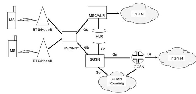
The GPRS network architecture reuses the GSM network nodes such as MSC/VLR, HLR, and BSC. It introduces two new network nodes for the transport of packet data: the Gateway GPRS Support Node (GGSN) and the Serving GPRS Support Node (SGSN).
Figure 10.3 3G GPRS architecture
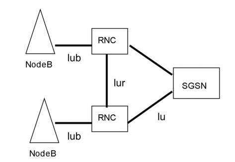
Figure 10.4 3G Radio interface
GPRS also defines new interfaces between the GSM network nodes and the different elements of the GPRS core network (see Figure 10.3).
This topic makes no distinction between acronyms that mean more and less the same thing. An example is 3G versus UMTS (Universal Mobile Telecommunications System). UMTS is one of the third-generation (3G) mobile telecommunications technologies, which is also being developed into a 4G technology. With UMTS, the BTS or NodeB still handles the radio access. Both packet-oriented services such as GPRS and circuit-switched services such as voice can use the same cell from the NodeB.
The BSC or a Radio Network Controller (RNC), as it is called in 3G, has the same function as in 2G, although some 3G functionality has been added to route voice traffic to circuit-switched networks and data traffic to packet based networks. RNC uses acronyms for its interfaces towards NodeB, all of which start with "lu" and a letter, for example, "b." Figure 10.4 shows the interface naming for radio elements.
The SGSN is the node that serves the MS. It delivers packets to and from the MS, and communicates with the HLR to register, to authenticate, and to obtain the GPRS profile of the subscriber. The SGSN also performs accounting. The SGSN can be connected to one or several BSCs or RNCs. Also, the SGSN is the device that manages mobility if the subscriber moves, finding the user’s "home" GGSN with assistance from the HLR. The SGSN functions very much the same way as the MSC does for voice. In a nutshell, the IP part from the SGSN starts with the packet service that the GPRS provides. In GPRS terms, the network interface between the SSGN and NodeB is called Gb.
A GGSN provides interworking with external Packet Data Network – (PDNs). The GGSN can be connected to one or several data networks, for example, to an operator’s Internet or to a company VPN. It connects to the SSGN using an IP-based GPRS backbone network, commonly called the mobile backhaul. The GGSN is a router that forwards incoming packets from the external PDN to the SGSN of the addressed MS, or vice versa. Once a packet leaves the GGSN towards a PDN, it is a pure IP packet. Thus, the other routers in the Internet or company VPN see the GGSN as just another router. The GGSN communicates with other services such as RADIUS to achieve the correct user profiles, and it also performs accounting.
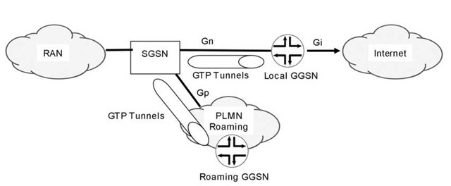
So how is the data traffic handled between the SSGN and GGSN? This is where the GTP (GPRS Tunneling Protocol) comes into the picture. The SSGN uses GTP to create a tunnel to the GGSN, which means that native IP processing of end user starts at the GGSN. Figure 10.5 illustrates GTP tunneling in the GPRS network.
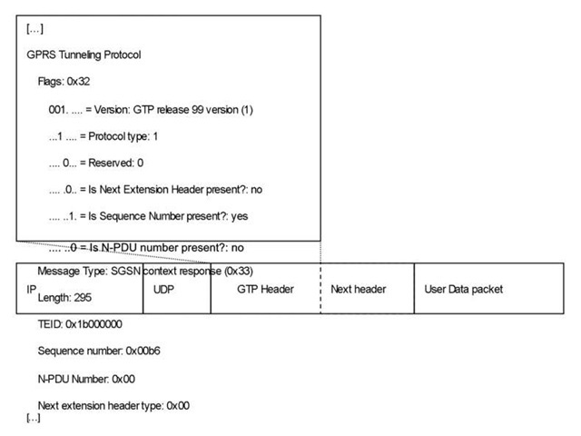
There are two types of GTP tunnels. The tunnel for control traffic, called GTP-C, uses UDP port 2123. The second type of tunnel, for user traffic, called GTP-U, uses UDP port 2152. Figure 10.6 shows the GTP header.
Control traffic over the GTP-U is exchanged between the MS and the GPRS network components to establish a PDP (Packet Data Protocol) context, defined in RFC 3314 [1]. The traffic over the GTP-U, which is the actual user traffic, is exchanged between the MS and the GGSN. The PDP context is the microflow entity for the user session. The mobile world does not talk about sessions; it talks instead about PDP context. Several PDP con-texts can be active between the MS and the GGSN.
Figure 10.5 GTP tunneling
Figure 10.6 The GTP header
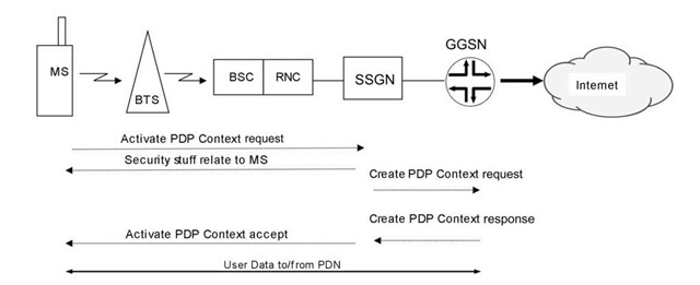
Figure 10.7 PDP context activation flow
The primary PDP context defines the connection to the GGSN, and the secondary context can have different attributes such as QOS because it can support different services. The PDP context can be seen as a mix between service and application, because each context established on the MS is assigned its own IP address. In this way, the PDP context is not similar to TCP, for example, which uses sockets and port numbers on the host itself to separate established applications from each other. Three basic actions can be performed on a PDP context: activation, modification, and deactivation. Figure 10.7 illustrates the PDP context activation.
Mobile users and their PDP contexts are grouped on the GGSN into an APN (Access Point Name). An APN is the mobile realm’s parallel of a VPN. The APN manages the IP address ranges that have been allocated to each PDP context. An example of an APN is Internet access or a private VPN, towards which the GGSN tunnels packets using IPsec or GRE tunnels.
