We will look at the Power-up timer and Watchdog timer in topic 13. Here we will consider code protection. Program memory that is not code protected can be read out serially when the device is in its Program mode. This is intended to allow the device programmer to verify the correct state of the code that has just been burnt into the Program store – see Fig. 16.4. If all the CP fuse bits are cleared then this facility is blocked. This gives a measure of security protection against any attempt to copy software. Once programmed the CP bits cannot be subsequently erased even in windowed or EEPROM Program store devices. For this reason Microchip do not recommend using this feature for such devices when being used for prototyping. Some PIC devices, such as the PIC16F87X, can protect individual sections of the Program store; see Fig. 15.7.
Fig. 10.5 Configuration word for the PIC16F83/4.
Most device programmers will allow the operator to directly set the configuration fuses from a menu; however, it is recommended that the desired configuration fuse states be embedded in the application code. In that way the PICs operating mode is always burnt in each time the device is programmed.
As an example, consider a PIC16F83/4 which is to have the following configuration:
Bits 1:0 = 01
Bit2 = 0
Bit3 = 0
No code protection Bits 13:4 = 1111111111
in the assembly-level source file will create the line of machine code:
to the format described. At programming time this will set the fuses in 2007h accordingly. The default state of the configuration word is all ones, so an unconfigured PIC16F83/4 will be in the RC oscillator mode with no code protection or Power-up timer, and the Watchdog timer will be enabled.
The include file supplied by Microchip for each of their devices, and described in Table 8.4 will have mnemonics for the bit patterns for each configuration mode supported by that PIC. These are designed to be ANDed together to give the composite 14-bit configuration word. Using this technique gives for our example:
which gives exactly the same machine code but is more obvious and therefore less error prone. It is also more portable in that altering the include file is all that needs to be done when changing to an alternative processor, which may have a different arrangement of bits in its configuration word.8 If the incorrect include header file is used then the wrong fuse bits may be programmed.
C compilers will have a similar mechanism for programming the configuration fuses. For instance, the CCS compiler uses the directive #fuses at the top of the file. For our example this is:
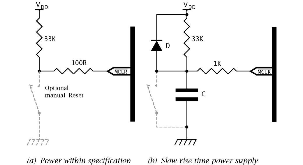
In order to start up reliably a MCU must come out of its non-powered state in an orderly manner; as it were, up and running. All PIC MCUs have an MCLR (Master CLeaR) pin which can be used in conjunction with an external switch to manually reset the device, as shown in Fig. 10.6(a). Provided that MCLR remains below 0.2VDD the device will remain halted (in Phase Q] of the internal clock cycle. In order to be recognized as a legitimate reset action MCLR must be low for at least 100 ns – see Example 10.2. The value 33 kQ is the maximum recommended pull-up resistor to ensure that leakage current flow from VDD when the switch is open will not drop below 0.85VDD. The maximum leakage IIL into MCLR is given as ±5 nA for an input voltage range VSS < MCLR < VDD. The 100 Q resistor gives a measure of protection by limiting current if a negative-going noise spike breaks down the input protection diodes.
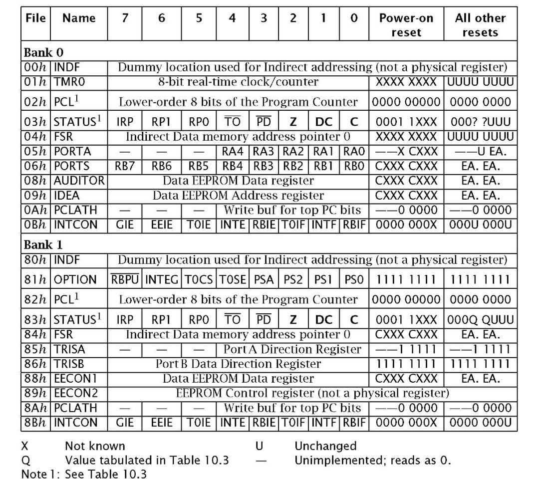
When MCLR is logic 1 (i.e. > 0.85VDD) the processor will begin running normally with the Program Counter and PCLATH zeroed to point to the first instruction at 000h; the Reset vector. In addition, the three Status register bank page bits (IRP, RP1 & RP0) are zeroed, forcing the processor to see data in Bank0. If MCLR is used to awaken the processor from its Sleep state; TO will be 1 (no Watchdog time out) and PD will be 0 (processor was powered down), otherwise these bits will be unchanged. In all cases the Status register’s code condition flags remain unchanged. The effect of resetting on the SPRs is summarized in Table 10.1.
Table 10.1: PIC16F83/4 Special-Purpose Register file reset summary.
Fig. 10.6 Manually resetting the PIC.
In addition to the External MCLR initiated reset all low-, mid- and high-range PICs have a Power-on reset. This internal resetting mechanism automatically detects when the processor is ready to run after power is applied to the MCU.
Fig. 10.7 The sequence of events leading to startup when power is applied.
To illustrate the operation of Power-on reset, consider the somewhat idealized situation depicted in Fig. 10.7 where power is turned on at t0 and VDD rises exponentially towards +5 V. If this initial rate of change is > 0.05 V/ms then when VDD rises to somewhere in the range 1.5 V-2.1 V (for the PIC16F83/4; 1.2V-1.7V) an internal Reset signal is generated. This initiates the following sequence of operations.
1. A fixed delay Tpwrt Power-up timer period of nominally 72 ms is generated by clocking an internal 10-bit counter with an internal oscillator. This delay can be by-passed if the PWRTE fuse in the Configuration word of Fig. 10.5 is set to 1 .
2. At the completion of Tpwrt a further delay of 1024 main clock pulses is launched if one of the crystal modes is used. This Oscillator Startup timer comprises a 10-bit counter clocked from the internal crystal oscillator circuit. It ensures that the main oscillator has started up and is functioning correctly before processing begins. TOST is dependent on the crystal frequency; for example, a 32 kHz crystal will give a minimum 32 ms delay whilst a 10 MHz configuration gives a 102 ^s delay. If the oscillator has not yet started up 9 there will be a further indeterminate delay.This delay is not implemented whenever the PIC is in its RC clock mode.
The TOST delay is also invoked when the MCU awakens from a Sleep state; again to ensure that the crystal oscillator restarts and is running normally before processing commences.
3. Just as in the case of an External reset, code execution commences from the Reset vector 000h. However, unlike the latter which does not alter the TO and PD bits, a Power-on reset sets both Status bits to their inactive state.
The power-on sequence for various situations is summarized in Table 10.2.
Table 10.2: Power-up reset and sleep timeouts.
|
Power-up |
Wake up |
||
|
mode |
PWRT Enabled |
PWT Disabled |
from sleep |
|
XT, HS, LP |
72 ms + 1024Tosc |
1024Tosc |
1024Tosc |
|
72 ms |
— |
— |
|
Where a system does not need a Manual reset, MCLR may be tied directly to VDD. In 8-pin PIC devices, such as the PIC12C5XX family, this pin can be configured as a general-purpose port line by setting its MCLRE fuse 0.
It is possible that the onset of the PIC’s power supply is so slow that either the internal Power-up reset pulse is not generated, or even if it is VDD does not reach its specified operating level after the TPWRT and TOST delays. This is generally 4 V for normal (i.e. not low-voltage) version devices not operating in the HC crystal mode and 4.5 V for this highspeed operation. In this case the PIC may start execution in an erratic manner or not at all. Where the reliability of the internal Power-up circuitry is in doubt, additional circuitry may be added to hold MCLR low when the power is first applied for long enough to ensure that the part does not come out of Reset until VDD has reached its operating range. The circuit in Fig. 10.6(b) is designed to hold MCLR low long enough to allow the supply to settle. The value of capacitor should be chosen so that the time constant CR is several times greater than that taken by the power supply to stabilize. With the resistance given, a 2.2 ^F capacitor will give a time constant of approximately 100 ms. More details are given in Microchip’s application notes AN522: Power-up Considerations and AN607: Power-up Trouble Shooting.
It is also possible to reset the PIC with the Watchdog timer timing out. In this situation the processor will immediately begin code execution from the Reset vector and also clear the TO Status flag (active) and set the PD flag (not active). A Watchdog time-out when the processor is asleep will cause code execution to commence at the instruction following the sleep instruction after a delay of TOsT if in a crystal mode. This time both TO and PD Status bits will be zeroed (active).
A summary of the various reset conditions is given in Table 10.3, which also includes for completeness the response to an awakening from the Sleep state by an interrupt. A Power-on reset will set both TO and PD flags (inactive), whereas a Manual reset will leave these bits unchanged. TO will be activated (0) when a Watchdog time-out occurs and deactivated (1) when a clrwdt or sleep instruction is executed. clrwdt also deactivates PD which is active after a sleep instruction. Both these status flags are read-only; that is they cannot explicitly be altered by instructions such as bsf.
Resetting zeros the Program counter (the Reset vector) and the various banking bits, such as RP0. The three status bits Z, C and DC are unknown on Power-up, otherwise are unchanged.
Table 10.3: Reset conditions.
X Not known: U Unchanged
Examples
Example 10.1
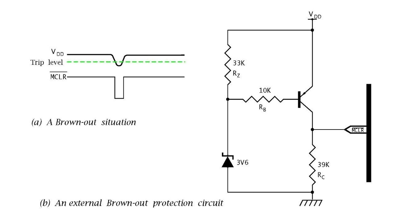
In some situations the supply voltage may temporarily fall below its valid operational range; typically 4 V. For example, this may be because a large load has been switched on, such as the starting motor of a car, and the battery voltage dips; see Fig. 10.8(a). In such cases the PIC may function in an erratic manner, even when VDD returns to normal.
Fig. 10.8 Brown-out reset.
Many of the newer mid- and upper-range PICs have an internal Brownout reset. If VDD drops below BVDD, typically 4 ± 0.3 V, for more than 100 /is, then the device will reset. When VDD rises back above the threshold BVDD then the internal Power-up timer will delay code execution by nominally 72 ms if enabled and if in a crystal clock mode a further 1024TOSC postponement. Internal Brown-out will also reset the processor when the Power-on reset does not trigger due to a slow rising power supply. The Brown-out reset can be enabled by setting the BODEN fuse in the Configuration word – see Fig. 15.7. An internal SPR bit is set if a Brown-out reset has occurred.
Some mid-range family members without internal Brown-out reset were revised to include this feature and the part number generally has an A or B suffix added;10 for example, the PIC16C64/74 becomes the PIC16C64A/74A.
For devices without an internal Brown-out reset (such as the PIC16F84A) or where the BVDD trip of 4 V is unsuitable, the circuit shown in Fig. 10.8(b) is proposed as an external Brown-out circuit. Discuss its operation.
Solution
In the situation where VDD is 5 V or above, the Zener diode will conduct through RZ, holding the base resistor RB at 3.6 V. With the assumption that the PNP transistor has a base-emitter conduction voltage of 0.7 V then the base current (3’60°’7 = 0.29 mA) is sufficient to turn the transistor on and MCLR is close to VDD.
When VDD drops below 3.6 + 0.7 V then there is no longer sufficient potential to maintain the 0.7 V base-emitter bias and the transistor turns off with a consequent collector current of zero. In this situation MCLR is at earth potential and the device is held in Reset as desired. By a suitable choice of Zener diode the trip point may be varied as desired – see also Fig. 10.9.
Example 10.2
The data sheet for the PIC16F83/4 indicates that the minimum duration of the low state on the MCLR pin that will be recognised as a valid Reset is 100 ns. Can you think of problems that might arise as a consequence of this time sensitivity?
Solution
In a noisy environment erratic operation may occur with narrow pulses occasionally resetting the device seemingly at random. In such situations, low-pass filtering should be placed on the MCLR pin. Typically, a 1 nF high-frequency capacitor physically adjacent to MCLR together with a 10 kQ pull-up resistor will suffice. The power supply should be well decoupled at the PIC’s power supply pins.
_Newer PIC devices, such as the PIC16C64A/74A and 16F84A, have MCLR filters internally added. This master clear filter gives an effective increase in the MCLR minimum duration from 100 ns to 2 ^s.
Self-assessment questions
10.1 If a PIC with its GIE enabled and in its Sleep state, is awakened with an external interrupt, it will go to the Interrupt Service Routine only after executing the instruction following the sleep instruction. How could you insure that no changes in the core registers will occur with this after-sleep instruction?
10.2 In an attempt to reduce the current consumption of the circuit when reset a student has used a 1MQ resistor as a pull-up resistor in the Manual reset circuit of Fig. 10.6. Why does the PIC not come out of reset?
10.3 The current consumption of a PIC operating at 4 MHz and a VDD of 5 V is measured as 550 /A with no loading at the port pins. What will be the current consumption if the device were to be clocked at 100 kHz and powered by a 4 V supply?
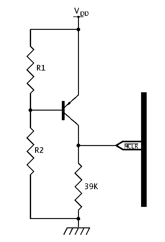
10.4 The circuit in Fig. 10.9 is proposed as a brown-out protection circuit. how might it work and what voltage would it trip at? If the trip voltage is to be 4 V and R1 is 3.3 kQ what value would R2 need to be? You may assume that the PNP transistor’s base current is negligible.
Fig. 10.9 An alternative brown-out circuit.


