Movement instructions
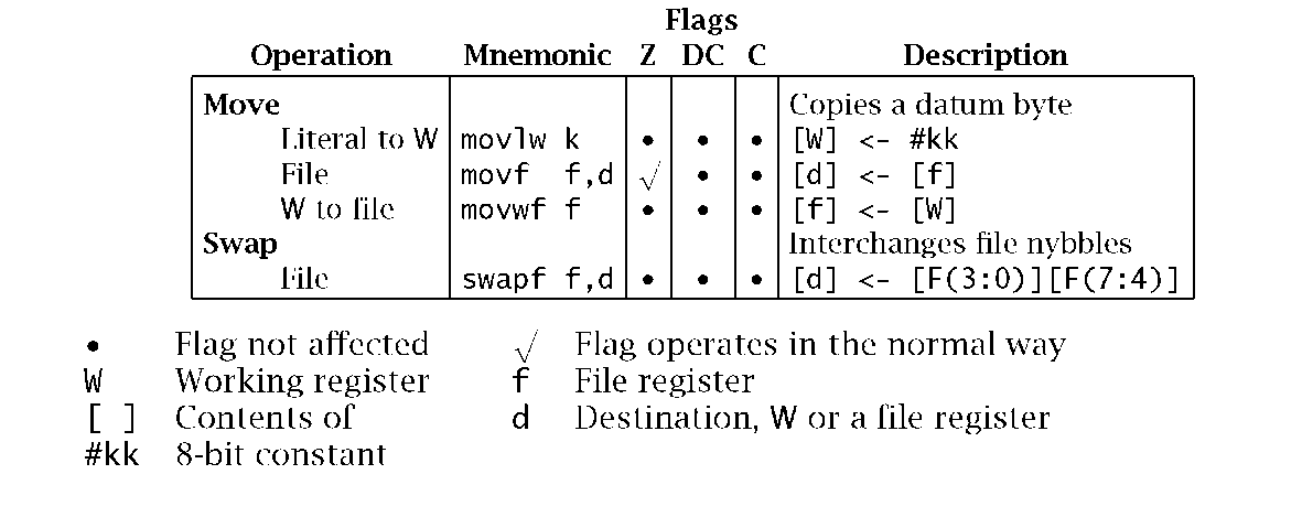
Around one in three instructions move data around without alteration. With this in mind the instructions in Table 5.1 will be the most used in the repertoire.
All three Move instructions can copy byte data to or from the Working register.
Table 5.1: Move instructions.
• movlw copies the specified 8-bit constant (or literal) to W. For example, movlw 80h initializes W to 10000000b. This instruction only affects the Working register and thus cannot be used directly to set up a file register to a constant value.
• movwf is used to copy out or store the contents of W into a register file. For example, the following code fragment will initialize the contents of File 22h to 80h:
• movf can copy (or load) the contents of any register file into W. For example, movf 22h,w loads W with the contents of File 22h. The destination of this instruction can also be the file itself, giving rise to seemingly useless instructions, such as movf 22h,f which copies the contents of File 22h back on top of itself! However, the process does activate the Z flag, which will be set if the file contents are zero, and of course this datum is not affected by the instruction. Thus movf FILE,f is equivalent to the missing tstf FILE instruction; that is TeST File for zero, that is commonly available in other MPU/MCUs. Thus the contents of any file register can be checked for zero by this means using a single instruction. An alternative technique needs to be used to test the contents of the Working register for zero.
Given that most instructions acting on a file can specify either the same file or the Working register as the destination, then a Move operation can be considered an implicit part of such instructions. As an example, for some situations to increment the contents of a file and then move it to W could be coded either as:
or
Of course the latter does not actually change the state of the file.
The final instruction swapf swaps the top and bottom 4-bit nybbles in a file. Thus, for example, if File 22h was 1001 0111b then swapf 22h,f will yield 0111 1001b. If desired, the outcome destination could be specified as W, eg. swapf 22h,w. As swapf does not affect any flag, this latter form can be used as a transparent replacement for movf 22h,w which does alter the Z flag. Of course it does interchange the two nybbles in the process.
Arithmetic
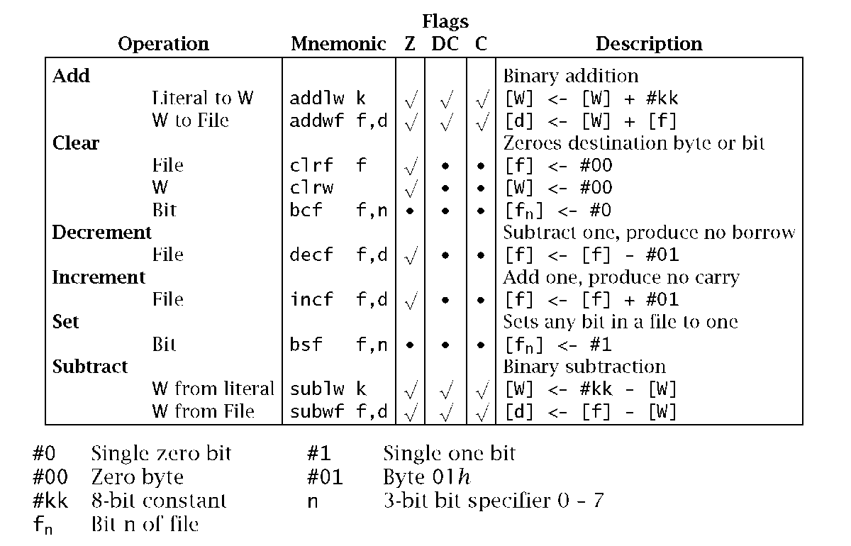
The PIC processors implement the normal byte-sized binary Add and Subtract instructions, to add or subtract register
Table 5.2: Arithmetic.
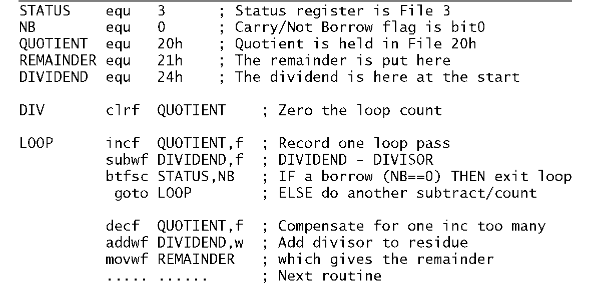
As an example that uses most of the instructions in Table 5.2 consider the problem of dividing the contents of File 24h by an 8-bit divisor in W. The simplest way of doing this is to continually subtract the divisor from the dividend, keeping a count until a borrow is generated. The residue left after this last subtraction is the remainder with one divisor subtraction to many. Thus adding the divisor once can restore the remainder if this is needed.
A possible implementation based on this approach is given in Program 5.3. Here the quotient is cleared before entering the loop, using the clrf instruction. The loop itself simply increments the quotient using the incf instruction and then subtracts W (the divisor) from File 24h -subwf 24h,f. Both Subtract instructions generate a complement borrow out, which is represented by the C flag in the Status register – labelled NB for Not Borrow in the program. Thus the loop is exited when the Carry flag is clear after the subtract, which represents a borrow out.
On leaving the loop, the contents of File 20h needs to be decremented, as the last subtract was one too many. Using the decf instruction allows this correction to be applied directly on the file register.
file contents to/from the Working register. In addition the W register may be added to or subtracted from an 8-bit constant.
Program 5.3 Division by repetitive subtraction.
The remainder can be determined from the residue left in the original dividend file. This represents one divisor subtracted too many. Thus, addwf DIVIDEND,w cancels this last action and this remainder outcome, now in W, is copied into File 21 h.
The addlw instruction can be used to add an 8-bit constant to W. Subtraction can also be carried out with this instruction by adding the 2′s complement of the literal subtrahend. For example. addlw F9h or addlw -7 will effectively subtract seven from the contents of W. Thus if [W] was 88h before this operation then the state of W after is 81 h:
Rather confusingly this is not the same as sublw 7 as this subtracts W from 7, that is [W] <- 7-[W] .
Although the arithmetic instructions act on byte operands, operations on word sizes of greater than 8-bit precision are possible with the help of the Carry/Not-Borrow flag. The process for the addition of two n-byte objects is given by the task list:
1. For = 0 to n – 1 DO
(a) Clear SUM.
(b) SUM[i] = NUM1 [i] + NUM2[i].
(c) IF Carry[i] = 1 THEN increment SUM[i+1].
(d) Increment i.
2. End.
Multiple-precision subtraction is carried out in a similar manner, using the Not-Borrow flag. Example 5.4 implements a 16-bit – 8-bit subtraction.
Data in memory can be incremented or decremented apparently in situ, although in reality it is transferred from the Data store into a temporary register, incremented or decremented using the ALU and transferred back to the Data store – a type of read-modify-write action. However, it still takes only one bus cycle to implement.
These instructions are especially useful in counting passes through a loop, as in Program 5.3 where QUOTIENT is located in the Data store at File 20h. However, incf is not quite the same as a addlf 1,20h type of instruction as it does not alter the state of the Carry flag. Thus if you wanted to increment a 32-bit number in Data memory at File 22:3:4:5h then this is how you would have to do it:
This depends on the algorithm IF when byte n is incremented it wraps around from FFh to zero THEN increment byte n + 1. See Example 5.1 for a multiple-precision decrement routine.
One of the more important operations is the comparison of the magnitude of the two numbers. Mathematically this can be done by subtracting the datum (designated [f] for either a register file or a literal) from the contents of the Working register [W]. The outcome gives the actual magnitude difference between the operands, but in most cases it is sufficient to determine the relative magnitude of the quantities – eg. is W higher than the datum? This is determined by checking the state of the C and Z flags in the Status register.
Working register higher than datum…………….No borrow, non-zero
Working register equal to datum………………………………..Zero
Working register lower than datum…………………Borrow, non-zero
In terms of our processor, the C flag represents the complement of the borrow after subtraction and the Z flag is set on a zero outcome. This gives:
| [w] Higher than or equal | [f] | [w]- | -[f] gives no borrow; (C = | 1). |
| [w] Equal to | [f] | [W]- | -[f] gives Zero; (Z = | 1). |
| [w] Lower than | [f] | [W]- | -[f] gives a borrow; (C = | 0). |
Consider as an example a fuel tank with a capacity of 2 5 5 liters, with a sensor at the bottom of the tank indicating the remaining volume of fuel as a linear function of pressure. Assume that the sensor represents the capacity as a byte that can be accessed at PortB, which we give the name FUEL. We wish to write a routine that will light an ‘empty’ light (at bit 0 at Port A) if the capacity is below 20 liters and ring an alarm buzzer (bit 1 at Port A) if below 5 liters. Both output peripherals are active on logic 0. This is how it could be coded:
After each subtraction the Carry/borrow flag will be logic 1 (that is no borrow) if the datum in the Working register (the fuel reading) is higher or the same as the literal being subtracted – it is being compared with. The addlw -k instruction can be replaced by the more obvious sublw k.4 Remembering that this subtracts W from the constant, that is k – W, then the following Skip on Set (btfss) instructions must be replaced by Skip on Clear (btfsc) to give the same sense of magnitude.
The contents of the Working register can be tested for zero in the same way, that is addlw 0 or sublw 0. If W were zero then the outcome of this tstw type of instruction will set the Z flag. We have already seen that the instruction movf xx,f can be used in the same way as a tst f instruction to test File xx for zero. Note the use of the bcf (Bit Clear in File) instruction to clear the appropriate bit in Port A, which we assume to be initially set to output. In the same manner the bsf instruction could be used to turn off the lamp and buzzer at the beginning of the routine.
Logic and Shifting instructions
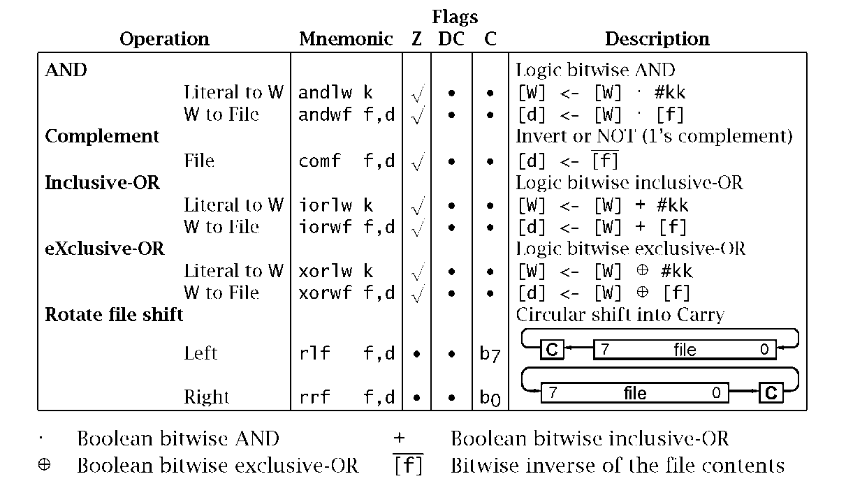
All four basic logic operations are provided, as shown in Table 5.3. The simplest of these is comf which inverts (or 1′s COMplements) all bits in a file register. For example:
Alternatively the outcome can be placed in W with the original contents being unchanged; eg. comf 22h,w. There is no instruction comw to explicitly invert the contents of the Working register, but this can be accomplished in one bus cycle by subtracting from 11111111k; eg. sublw 0FFh: For example:
Table 5.3: Logic instructions.
The andwf instruction bitwise ANDs the Working register together with the contents of any file register, with the outcome being placed either in that same file or in W. Similarly the andlw instruction bitwise ANDs W with a byte literal.
ANDing an input with a 0 always gives a 0 output, whilst with a 1 does not change the logic value. For example:
Another use of ANDing is to check the state of any bit or bits in a datum; for example:
By ANDing the Working register with 11000000b, the outcome will be all zero only if both bits 7 and 6 of W are 0. In this case the Z flag will be set and the following Bit Test File Skip on Clear will not be taken and the program will transfer to ALL_ZERO. If a single bit in a file register is being tested for zero then the btfsc instruction (see Table 5.4) is a more efficient process.
The iorwf and iorlw instructions implement the Inclusive-OR operation in the same way as for AND. ORing with a 0 leaves the source bit unchanged whereas ORing with a 1 sets the bit to a 1 irrespectively. Thus ORing is normally used to set any group of bits in the destination operand. For example:
sets the two least significant bits to one.
The xorwf and xorlw instructions provide for the eXclusive-OR operation.XORing with a 0 leaves a data bit unchanged, whilst XORing with a 1 inverts (or toggles) that bit. Thus, for example if we wished to invert both bits 0 and 7 of W: For example:
Another use for XOR is to isolate changes between two bit patterns.Consider as an example a program routine that continually monitors Port B to which has been connected eight switches. This routine is waiting until someone moves a switch.
The outcome in W reflects any changes. In the first case there are no differences between the latest sample and the original switch settings put away in File 20h. In the second situation Switch4 has just been thrown from 1 to 0. You can determine which switch changed by shifting the outcome (the change byte) right, counting until the residue is zero. You can also determine the type of change (0 — 1 or 1 — 0) by ANDing the change byte to the original switch settings in File 20h, i.e. andwf 20h,w. If the outcome at bit 4 is a 0, then the change must have been 0 — 1, and vice versa.

![tmp18316_thumb[2] tmp18316_thumb[2]](http://what-when-how.com/wp-content/uploads/2011/06/tmp18316_thumb2_thumb.png)
![tmp18317_thumb[2] tmp18317_thumb[2]](http://what-when-how.com/wp-content/uploads/2011/06/tmp18317_thumb2_thumb.png)
![tmp18318_thumb[2] tmp18318_thumb[2]](http://what-when-how.com/wp-content/uploads/2011/06/tmp18318_thumb2_thumb.png)


![tmp18321_thumb[2] tmp18321_thumb[2]](http://what-when-how.com/wp-content/uploads/2011/06/tmp18321_thumb2_thumb.png)
![tmp18322_thumb[2] tmp18322_thumb[2]](http://what-when-how.com/wp-content/uploads/2011/06/tmp18322_thumb2_thumb.png)
![tmp18323_thumb[2] tmp18323_thumb[2]](http://what-when-how.com/wp-content/uploads/2011/06/tmp18323_thumb2_thumb.png)
![tmp18324_thumb[2] tmp18324_thumb[2]](http://what-when-how.com/wp-content/uploads/2011/06/tmp18324_thumb2_thumb.png)
![tmp18325_thumb[2] tmp18325_thumb[2]](http://what-when-how.com/wp-content/uploads/2011/06/tmp18325_thumb2_thumb.png)

![tmp18327_thumb[2] tmp18327_thumb[2]](http://what-when-how.com/wp-content/uploads/2011/06/tmp18327_thumb2_thumb.png)
![tmp18328_thumb[2] tmp18328_thumb[2]](http://what-when-how.com/wp-content/uploads/2011/06/tmp18328_thumb2_thumb.png)
![tmp18329_thumb[2] tmp18329_thumb[2]](http://what-when-how.com/wp-content/uploads/2011/06/tmp18329_thumb2_thumb.png)
![tmp18330_thumb[2] tmp18330_thumb[2]](http://what-when-how.com/wp-content/uploads/2011/06/tmp18330_thumb2_thumb.png)
