If you like to think of writing a program as analogous to preparing an elaborate meal, then for any given cooking appliance, such as a microwave oven or electric stove (the hardware) there are a range of processes. These processes – for example, steaming, frying, boiling – are analogous to the instruction set which can be implemented by the CPU. The various ingredients that can be handled by a process are the instruction’s data. Such data may lie in an internal register or out in the Data store. There are several different ways of specifying the effective address (ea) of an operand. These are known as address modes.
In keeping with the PIC microcontrollers’ RISC-like philosophy, the mid-range core have a total of only 35 instructions. Each instruction code is contained in a 14-bit word which holds the instruction operation code, address or data and destination bit. We have covered most of these instructions and address modes when discussing our BASIC computer back in topic 3; now would be a good time to go over this material. As we will begin this topic by examining PIC’s address modes and how they are incorporated into an instruction’s binary word, we will use BASIC’s instruction set listed in Table 3.1 for our illustrative examples. The latter part of the topic looks at the full instruction set in some detail.
After reading this topic you will:
• Know that an address mode is the way an instruction pin-points its data.
• Understand how Inherent, Literal, Register Direct, File Direct, File Indirect, Bit and Absolute address modes permit an instruction to target an operand for processing.
• Know that Movement instructions, copying data in-between the Working register and the Data store, are the most used of the instruction categories.
• Appreciate that the processor can directly implement the common arithmetic operations of Addition, Subtraction, Incrementation and Decrementation.
• Know that data in the Data store can be rotate-shifted through the C flag.
• Understand how to use the four basic logic instructions to invert, set, clear, toggle, bit test and differentiate data.
• Know how to compare or test data for differences and relative magnitude, and take appropriate action.
• Understand how the program flow can be diverted, based on the state of any bit or a zero value in a Data file.
• Recognize how the binary structure of the instruction word impacts on the usage of instructions.
Virtually all instructions act on data; either outside in its Data or Program memory space, or inside in an internal CPU register. Thus the 14bit instruction code must include bits which inform the CPU’s instruction decoder where this data is being held. The exception to this are the few Inherent instructions, such as nop (No Operation) and return (RETURN from subroutine). Before looking at the instruction set we will discuss the various techniques used to specify the location of any operands.
The general symbolic form of an instruction is:
where operand A is the source data or its location and operand B the destination. For example movf 20h,w (MOVe File) which copies data source out of File 20h to its destination in the Working register.
There are some variations on this structure. 21-operand instructions are common. For example, addwf FILE,d adds the W register’s contents to the specified file’s contents and deposits the result either in W or back in the file register itself. Thus addwf 20h,f means "add the contents of W to that of File 20h and put the outcome in File 20h" or in Register Transfer Language (f20) <- W + (f20). Of course this is not a true 3-operand instruction as the destination must be one of the two source locations; that is W or File 20h. A few instructions have only a destination specified; for example, clrf 20h, and the inherent instructions have no explicit operands.
Instructions can be classified by their address mode.
Inherent
The instructions listed in topic A, clrwdt (CLeaR WatchDog Timer), retfie (RETurn From Interrupt and Enable), nop, return and sleep do not explicitly refer to operands in memory or in the Working register. At the binary code level, all these instructions are coded with the upper seven bits zero. For example, clrwdt has a machine code of 00000000000100b.
Register Direct
The PIC series has only one CPU register that can be explicitly specified by an instruction; the Working register. Where the destination is to be W then bit 7 of the instruction code is always 0. For example clrw is coded as 0000000000011 b. Many instructions can either use W or the source file as the destination, and this is coded by setting bit 7 to 0 or 1 respectively. In topic A, bit 7 is marked as d for destination (see also File Direct addressing) for applicable instructions.
Where W is one of the source operands, the instruction normally shows this as part of the mnemonic. Thus movwf f copies W to the specified file register.
Literal
Literal instructions use the lower eight instruction word bits to specify a source operand which is constant data rather than data in a register. For example addlw 06 is coded as 11111000000110b. The destination of this type of instruction is always the Working register, and this is shown in the mnemonic. Thus in our example, the sum W + 6 is copied back into W. In rtl this is expressed as W <- W + #6 where the # (pound or hash) symbol denotes that the following number is a constant or literal rather than a file address.
File Direct
Instructions that specify that their source or destination operand lies in a file register use this address mode. The value of the file address is coded into the lower seven bits; denoted as fffffff. For instance the code for clrf 20h is 00 0001 10100000.
Most instructions altering the contents of a file register can ‘dump’ the outcome either in the Working register or else back in the file. Bit 7 of the instruction code, labelled d, can specify the destination as in the following example:
In both cases the contents of File 20h (File 01000000b) are incremented. In the former instance, the outcome is put in W leaving the file contents unchanged (d = 0), whilst in the latter the original data is overwritten (d = 1 ).
The main characteristic of this type of address mode is that the location of the operand is fixed as an integral part of the program, and thus cannot be altered as the program progresses. In some cases, such as in Program 5.1, this technique is rather inflexible.
As only seven bits of the instruction code are reserved for the file address, only files from 00 – 7Fh may be directly accessed using this technique. However, from Fig. 4.6 we see that the PIC16F84′s Data store maps the register files in the range 00 – FFh, requiring an 8-bit address. The PIC16F84 gets round this by employing the RP0 bit in the Status register as a surrogate most-significant address bit.
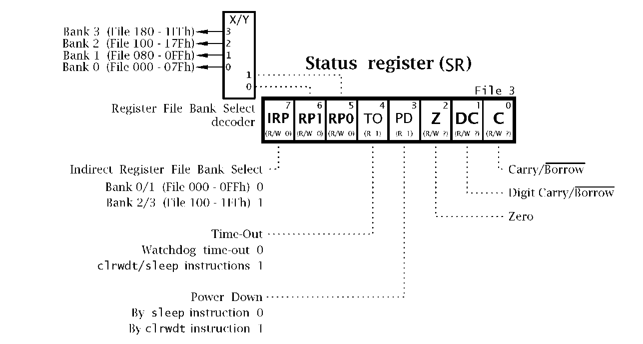
The full 14-bit core CPU model has the capability of interacting with a 512-register file Data store. Devices with this size of Data store, such as the PIC16F87X line, have to deal with four banks of up to 128 register files. This requires a 9-bit address. Here the Status register, shown in Fig. 5.1, RP1:RP0 which must be set up prior to using the File Direct address mode. For example, in such a Data store with a file address range 000 – 1FFh, in order to clear File 17Fh (File 10 111 1111b) we need to set RP1:RP0 to 10:
Program 15.4 is an example making use of this extended bank switching.
File Indirect
Where data in the Data store is to be accessed, specifying its location directly as an address constant seems the obvious way to go; for example, clrf 20h. However, as we saw back in Program 3.1, this may not always be the most efficient approach. This is especially the case when an array of data, such as a sequential set of readings, is to be processed.
Most MPU/MCU devices have one or more Address registers, sometimes known as Index registers. These are designed to hold the address in memory of the operand; that is they act as a pointer. Such processors use one or more Indexed or Indirect address modes which look to the appropriate pointer register to specify the operand location, rather than have the address as a fixed part of the instruction code. The advantage of this indirect approach of addressing a data operand is that the address can easily be altered as the program progresses. Thus, for example, an array of data may be cleared by using an address register to point to the target location, and repeating in a loop while incrementing that pointer register.
Fig. 5.1 General 14-bit core Status register.
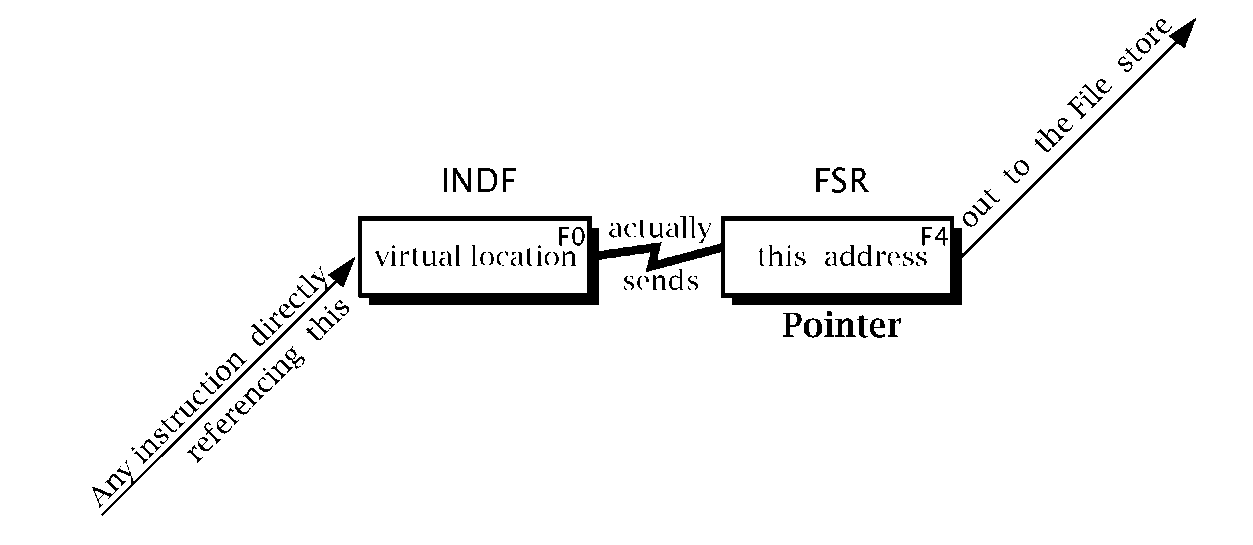
The PIC family does not have dedicated CPU Address/Index registers to perform this indirect holding function. Instead, the pointer address is that contained in the File Select Register (FSR), which is File 4 in the Data store, see Fig. 4.6,To activate the indirect mechanism, the normal File Direct address mode is used, but with File 0 as the target location. File 0, the INDF (INDirect File) register, is a virtual location, that is it is not physically implemented. Its sole use is to trigger the use of the contents of the FSR as the operand address, as shown in Fig. 5.2. Thus the instruction clrf 0 will actually clear the file whose 8-bit address is that in File 4. Of course the contents of the Special-Purpose Register (SPR) FSR can be altered at any time, for example incremented on each pass through a loop. This is the approach taken in Program 3.2, which clears an array of Data-store memory. Although this approach to indirect addressing may seem rather convoluted, it does not require additional clock cycles to execute, unlike the alternative techniques used by other MPU/MCUs.
Fig. 5.2 The indirect mechanism.
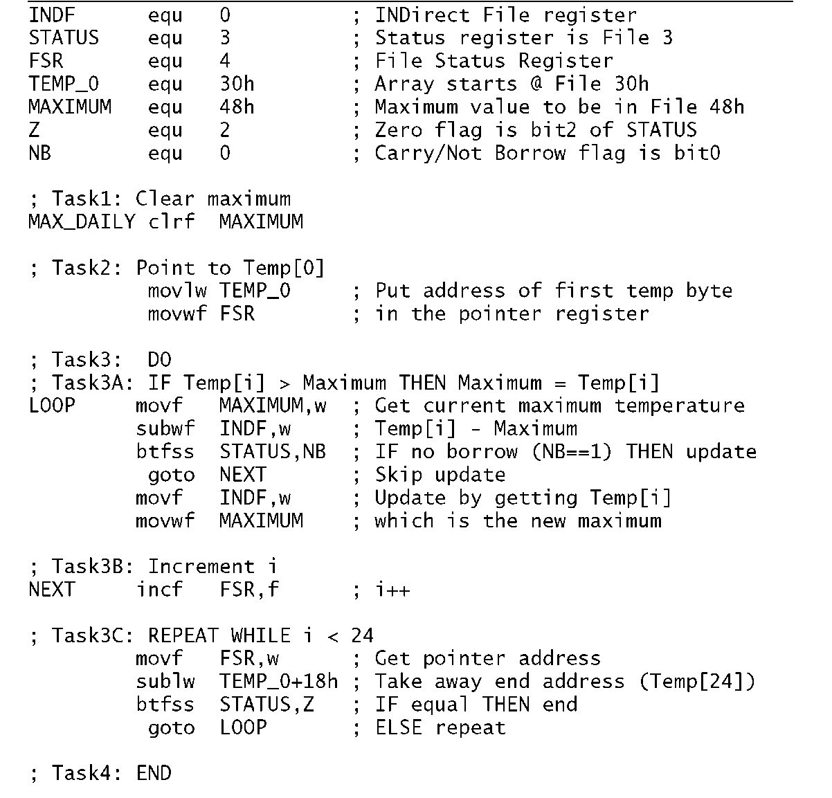
A more sophisticated example than that of Program 3.2 involves the sampling of temperature hourly over a daily period. With the assumption that the resulting array of 24 byte values are in situ in the Data store between File 30h and File 47h, we are required to scan through the array looking for the maximum temperature. By the end of the routine this is to be in File 48h.
To implement this procedure we first need a strategy or task list. One possibility would be:
1. Initialize Maximum as Temp[0].
2. IF Temp[1 ] > Maximum THEN Maximum = Temp[1 ].
3. IF Temp[2] > Maximum THEN Maximum = Temp[2].
4. IF Temp[3] > Maximum THEN Maximum = Temp[3]…….
5. …etc.
6. IF Temp[23] > Maximum THEN Maximum = Temp[23].
7. End.
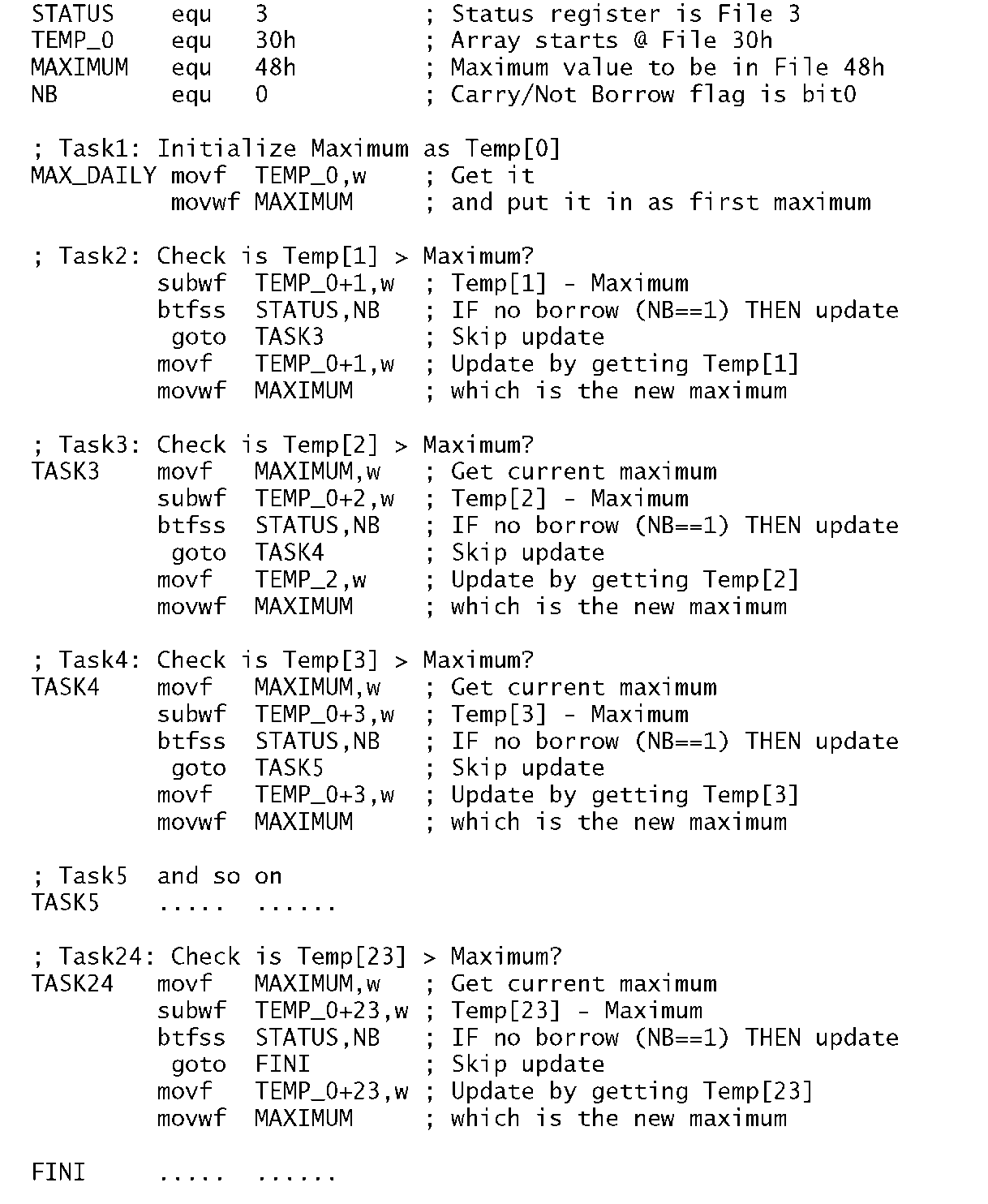
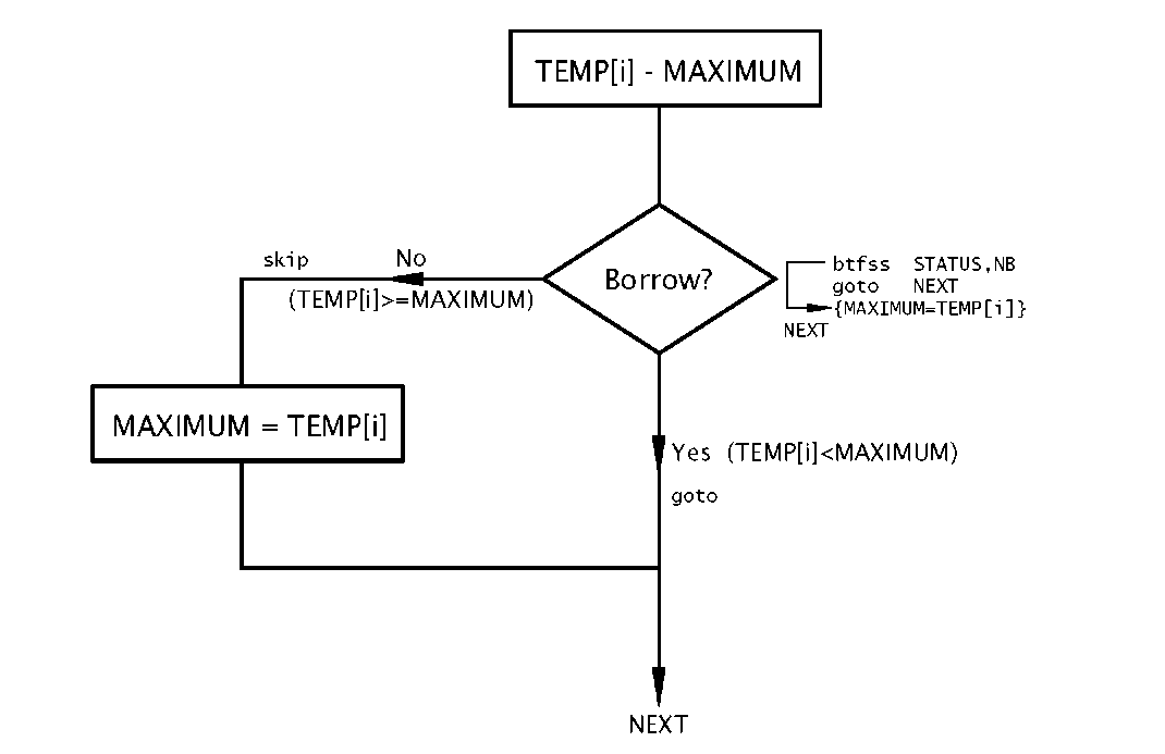
How can we code Temp[i] > Maximum? If we subtract Maximum from Temp[i], that is Temp[i] – Maximum, then if a borrow is not generated (C flag set) we know that the former is higher than the latter and Maximum needs updated. Based on this, a possible coding is given in Program 5.1.
In this linear coding the comparison is implemented by first bringing the current maximum into the Working register (movf MAXIMUM,w), then subtracting it from the appropriate direct address, eg. for Temp[2] or File 32h, subwf TEMP_0+2,w. This subtraction will set the C flag (that is N) if there is no borrow out, and in that situation the instruction btfss will skip to the update sequence. This simply copies down the appropriate temperature byte and copies it again up to the register file holding Maximum, eg. movf TEMP_0+2,w – movwf MAXIMUM.
The process outlined here has to be coded 24 times, with some small saving in the initial setting of Maximum to Temp[0] and the fact that this value is already in W for the Temp[1] comparison. This gives a total of 139 instructions. Execution time depends a little on the number of times Maximum has to be updated. However, taking a worse-case scenario and remembering that goto takes two cycles to implement as does btfss
Program 5.1 Finding the maximum temperature the linear way.
when a skip occurs, then this gives 188 clock cycles to execute; that is 188 /us for a 4 MHz crystal.
Now Program 5.1 is rather a long program for a small task. This is because the complete sequence of compare-update instructions have to be implemented 23 times. Each sequence is identical, except the next element in the temperature array is tested each time. A much more efficient approach is to execute this sequence inside a loop and use an advancing pointer to target Temp[i] as the process unfolds. This technique leads to the task list:
Fig. 5.3 The ith section of the compare-update sequence.
1. Clear Maximum.
2. Point to Temp[0] (i = 0).
3. DO
(a) IF Temp[i] > Maximum THEN Maximum = Temp[i].
(b) Increment i.
(c) Repeat WHILE i < 24.
4. End.
The implementation of Program 5.2 uses the same compare-update sequence, but this time with the Indirect address mode to access the data byte Temp[i]. The contents of the File Select Register here holds the address of Temp[i] and is initialized in Task2. After each loop pass, this pointer is incremented and then compared by subtraction from the first address beyond the array; that is TEMP_0 + 24. If they are equal then the Z flag will be set and the goto LOOP instruction skipped over out of the loop.
This Indirect mode coding takes 14 instructions; that is 10% of the linear version. However, it does take rather longer to execute, due to the overhead of incrementing the pointer1 and checking for range on each loop pass. The worst-case run time is 291 ^s against 188 s, assuming a 4 MHz crystal.
Program 5.2 Finding the maximum temperature using a loop structure.
One advantage of the Indirect address mode is that the pointer address is eight bits wide. Thus it is not necessary to use the RP0 bit to switch between BankO and Bank 1 of the Data store. The full 14-bit core model allows for four 128-byte banks of register files. The Status register of Fig. 5.1 shows the IRP bit which is used for family members with three or four register file banks. In such a device, if the temperature array of Program 5.2 were located in File 130h through File 147h then IRP would need to be set to 1 at the beginning of the routine (bsf STATUS,7) and cleared at the end. The rest of the code is unaltered. Microchip recommend that the IRP (and RP1) bits in the Status register are left in their zero reset state in family members, such as the PIC16F84, that do not have data storage above Bank 1.
Bit
Four instructions (as specified by the two ?? bits above) either alter or test the state of a single bit within a register file. In this situation the instruction word has an embedded 3-bit code nnn defining the bit number from 0 through 7, as well as the file address coded in the normal way. Thus the instruction bcf 20h,7 (Bit Clear bit7 in File20h) is coded as 01 00 111 0100000. The other instructions are bsf (Bit Set in File, coded as 01), btfsc (Bit Test File and Skip if Clear, coded as 10) and btfss (Bit Test File and Skip if Set, coded as 11 ).
Absolute
This 11-bit address can directly locate any instruction in a Program store of up to 211 = 2 Kbyte capacity. However, the mid-range core has
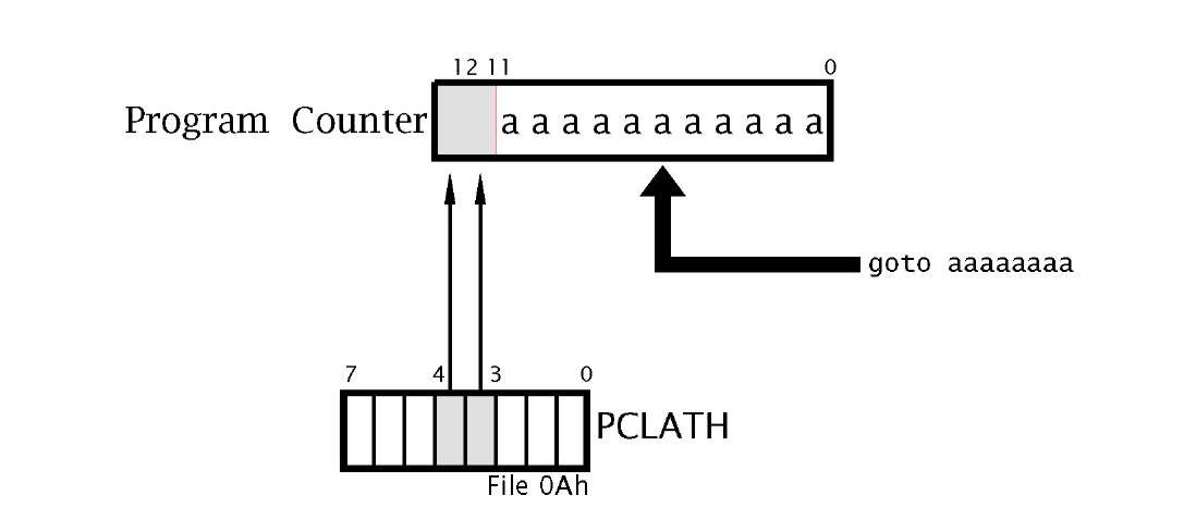
Two instructions allow the program to jump to another instruction anywhere in the Program store. These are goto and call (CALL or goto a subroutine, see topic 6). The 14-bit core allocates eleven bits of the instruction word to this absolute instruction address2 in the Program store. Thus goto 400h would be coded as 10 1 10000000000. Similarly call 530h is 100 10100110000.
Fig. 5.4 Generating a 13-bit Program-store address for the goto and call instructions.
a 13-bit Program Counter which can potentially address a Program store of up to 8 Kbyte instructions; for example the PIC16C74 has a 4 Kbyte store. To cope with this situation, when a goto or call instruction is executed, the absolute 11-bit address is transferred into the PC together with bits 3:4 of the PCLATH (Program Counter LATch High) to make up an effective 13-bit Program-store address. This process is shown in Fig. 5.4 – see also Fig. 4.3.
PCLATH is cleared on Reset, so the goto range is normally 000 – 7FFh. This covers all the address range for a 2 Kbyte store. For members with larger Program stores then a far goto and far call (i.e. beyond 7FFh) has to be implemented by twiddling bits PCLATH[4:3]. For example, in the PIC16C74 a goto 800h is coded as:
So far we have classified instructions by the method they pin-point their operands. The alternative approach is to catalog the instruction set by function. On this basis the 14-bit core PIC’s instruction set can conveniently be divided into six groups, of which four will be examined here. Those relevant to subroutines and interrupts are listed in the next two topics, and control instructions pertaining to internal operation of the MCU hardware are left to topic 10. The complete instruction set is given for reference in topic A.


