Solution
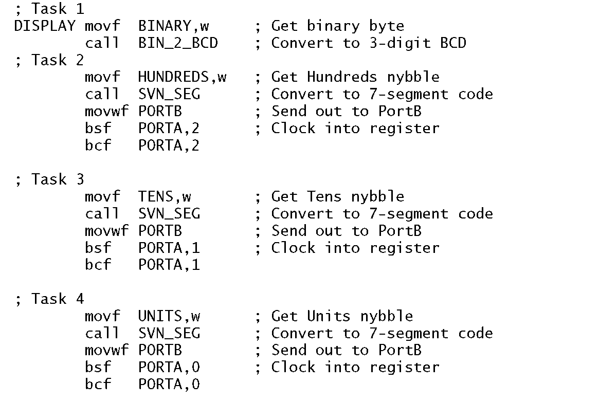
From the software perspective two main functions can be identified. Firstly the binary code in File 20h has to be decomposed into three BCD digits; HUNDREDS, TENS and UNITS. Once this is done then each BCD digit ranging from 0-9 must be converted to 7-segment code to illuminate the relevant segments to form the appropriate characters. We already have a subroutine to implement the former in Program 6.10 and the latter in Program 6.4.Based on this code in situ, we have as a task list for software to interact with the hardware of Fig. 11.13:
1. Convert the binary byte into BCD.
2. DO
(a) Copy contents of HUNDREDS into W and convert to 7-seg.
(b) Copy 7-segment code to Port B.
3. DO
(a) Copy contents of TENS into W and convert to 7-seg.
(b) Copy 7-segment code to Port B.
4. DO
(a) Copy contents of UNITS into W and convert to 7-seg.
(b) Copy 7-segment code to Port B.
The coding implementing this task list is shown in Program 11.7.
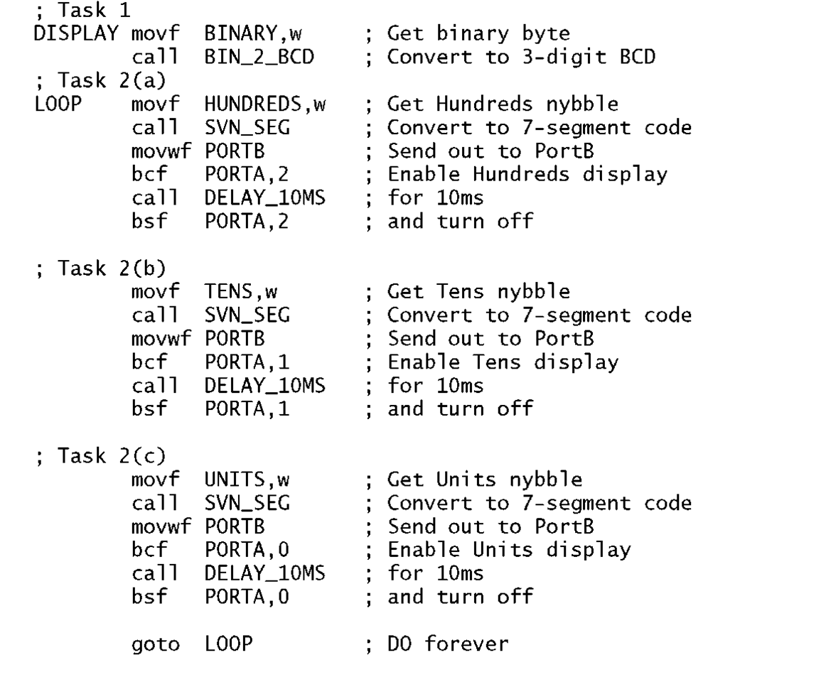
The interaction of the software to the hardware of Fig. 11.14 is not so straightforward as there are no registers to dump the data and run! Instead, data has to be continuously sent out in sequence with the appropriate display being enabled. If we use a scan rate of 100 updates each second then this data should be held for 10 ms before moving on. Thus we have as our new task list:
1. Convert the binary byte into BCD.
2. DO forever:
Program 11.7 Displaying the decimal equivalent of a binary byte.
• Copy contents of HUNDREDS into W and convert to 7-segment code.
• Copy 7-segment code to Port B.
• Delay 10ms.
(b)
• Copy contents of TENS into W and convert to 7-segment code.
• Copy 7-segment code to Port B.
• Delay 10ms.
(c)
• Copy contents of UNITS into W and convert to 7-segment code.
• Copy 7-segmentcode to Port B.
• Delay 10ms.
The coding in Program 11.8 makes use of the 10 ms delay subroutine illustrated in Program 11.5 to regulate the scanning rate. Apart from the length of the enabling pulse the core of the program is identical to our previous situation. However, the code must run continually to give the impression of a constant display. This illustrates the trade off between hardware and software. Reducing the hardware has lead to greater load-ing on the software. Indeed, as illustrated here the entire existence of the PIC will be to service the display! However, in practice the situation can be redeemed somewhat by interrupting the PIC at 10 ms intervals to avoid the need for time-wasting delay routines.Alternatively an external 100 Hz oscillator can be used in its place, but some of the hardware advantages are then lost.
Program 11.8 Displaying a 3-digit decimal number on a scanning readout.
Another issue that can occur with scanning, is noise introduced by switching on relatively large currents on a continual basis. This can be a particular problem where analog circuitry is adjacent. Good power-supply decoupling can reduce this problem to some extent.
Self-assessment questions
11.1 One problem with the intruder alarm configuration of Fig. 11.10 is the need to cable the Zone ports with eight conductors plus one per zone. An alternative approach would be to replace each zone’s 3-state buffer by a PIC. Each PIC would drive a 4-wire common bus back to the main base PIC. One wire can be used as a shared handshake line to signal the base that an intruder has been sensed at the zone indicated on the three data wires.
Show how a PIC16F84 could be configured as a Zone PIC paying particular attention to the usage of the single handshake line shared with all zones.
Would it be possible to reduce the number of wires to three? How could a local display be added to show which sensor has been set off?
11.2 A certain PIC running at 20 MHz has its Port C connected to LEDs tied high through a 1 kQ resistor and with a 300 pF capacitance to ground. All LEDs are off and the programmer attempts to turn on LED 7 and LED 0 as follows:
However, only LED 0 actually turns on. What is happening?
11.3 A certain system needs to be able to both activate eight LEDs and to be able to read the state of up to eight normally-open (N.O.) push switches. It has been proposed that a single PortB might be able to combine these functions – the former when set to output, the latter when set to input. Can you devise a suitable circuit?
11.4 A PIC-based reaction meter is to be designed to act as a crude blood-alcohol level indicator. The principle of the device is that a buzzer is sounded for 100 ms when the unseen tester closes his or her switch. The subject is to respond to the sound by immediately pressing his/her switch. An 8-LED barograph display is to indicate the passage of time by progressively illuminating an additional LED every 50 ms. The number of lit LEDs at the conclusion of the test is the reaction time in 50 ms steps.
Show how a PIC16F84 could be configured in hardware and software to read both switches and activate the eight LEDs and one buzzer.
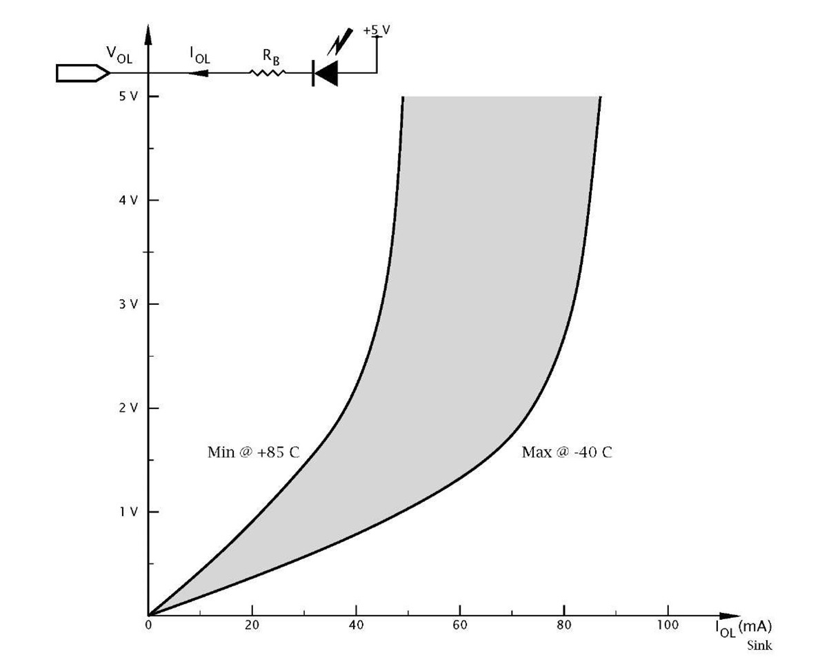
11.5 The variation of logic 0 output voltage VOL against sink current IOL for the two extremes of the commercial temperature range is shown in Fig. 11.15. Using this graphical relationship determine the maximum value of series resistor to ensure a current of no less than 20 mA will flow through an LED connected to +5V, as shown in the diagram, for any temperature. With this value what will be the current be at -40°C? You can assume that the conducting voltage across the LED is a constant 2 V.
Fig. 11.15 Low-level output voltage against sink current.
11.6 Repeat the exercise of SAQ 11.4 but coding in C.
11.7 Extend the digital comparator of Example 11.2 to compare two external digital bytes presented to a 28-pin footprint PIC, with byte P being input at Port B and Q at Port C.
11.8 In a low-power wireless data logging system placing the PIC in its sleep mode will not affect the current consumption of the radio transmitter. It is proposed to use a port pin to supply current to the transmitter and in way this auxillary circuitry can be switched on and off as necessary. Discuss.

![tmp9160_thumb[2][2][2][2] tmp9160_thumb[2][2][2][2]](http://what-when-how.com/wp-content/uploads/2011/06/tmp9160_thumb2222_thumb.png)
![tmp9162_thumb[2][2][2][2] tmp9162_thumb[2][2][2][2]](http://what-when-how.com/wp-content/uploads/2011/06/tmp9162_thumb2222_thumb.png)

![tmp9166_thumb[2][2][2][2] tmp9166_thumb[2][2][2][2]](http://what-when-how.com/wp-content/uploads/2011/06/tmp9166_thumb2222_thumb.png)

