Example 12.4
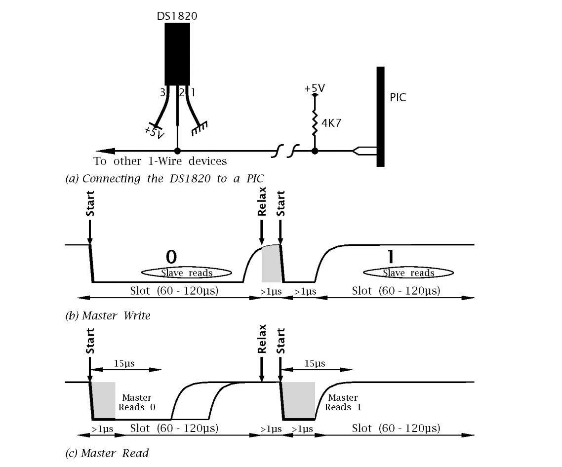
It is possible to combine some of the attributes of synchronous I2C and asynchronous signalling to send data asynchronously in both directions half-duplex along a single link. One example of this is the 1-Wire11 interface outlined in Fig. 12.24.
Fig. 12.24 Interfacing the DS1820 1-Wire digital thermometer.
In Fig. 12.24(a) a Dallas Semiconductor DS1820 digital thermometer is shown driven from a single port line with the MCU acting as a 1-Wire Master.
The DS1820 has the following features.
• Measures temperature from – 55°Cto+125°Cin0.5°Cstepsasa signed 16-bit datum.
• Converts temperature in 500 ms maximum.
• Zero standby current.
• Can be powered in certain limited circumstances from the data line.
• Multidrop capability.
The various DS1820 functions, such as Convert (44h), Read temperature (BEh), are initiated by the Master sending the appropriate data as 8-bit codes, each byte comprising a Start condition![]() and eight Write slots, as shown in Fig. 12.24(b). As in the I2C case, the data line DQ is pulled high with a pull-up resistor and the Master simulates the logic 1 state by changing its port line from low to input (see Fig. 12.14(b)). In this state the Master can listen to data sent by the Slave as shown in Fig. 12.24(c).
and eight Write slots, as shown in Fig. 12.24(b). As in the I2C case, the data line DQ is pulled high with a pull-up resistor and the Master simulates the logic 1 state by changing its port line from low to input (see Fig. 12.14(b)). In this state the Master can listen to data sent by the Slave as shown in Fig. 12.24(c).
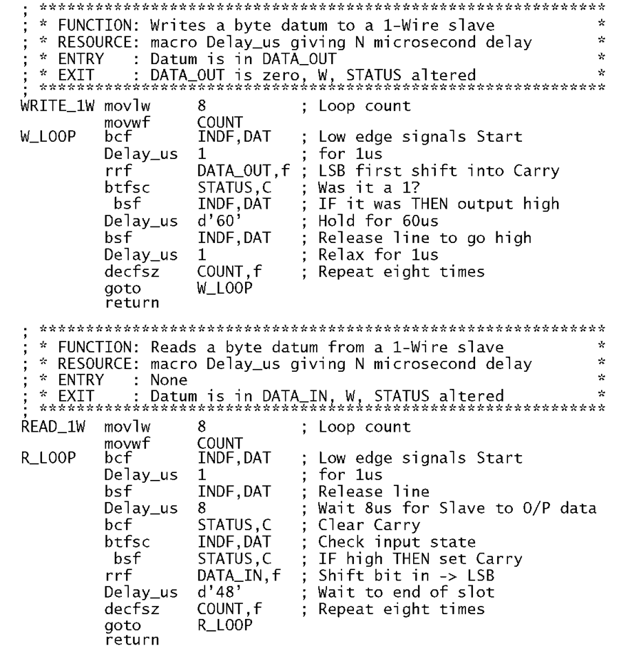
For our example we are required to write two subroutines that will respectively write a byte to a 1-Wire Slave and read a byte from the Slave.
Solution
From Fig. 12.24(b) we see that writing a bit to a Slave involves the following tasks:
1. The Master starts the process by forcing the data line low for at least 1 /is.
2. The Master either keeps the line low (Write 0) or releases the line (Write 1) for 60 – 120 is.
3. The Slave reads the line state between 15 – 45 is later.
4. The Master releases the line (if Write 0) for at least 1 is to relax the system.
Also we assume that we have the delay macro De1ay_us in situ which gives a K/s delay, where K is the parameter passed to the macro.
Both subroutines begin by driving DQ low for a minimum of 1 iS, defining the Start condition. Writing a single bit to DQ occurs in a slot which has a duration of 60 – 120 is, and commences with DQ either low or released to be pulled high, defining a Write-0 or Write-1 condition. The Slave samples the state of the data line sometime after 15 is into the slot. Although the duration of the slot is not critical, care needs to be taken as a low duration of between 480 and 960 is is interpreted by the Slave as a Reset command (see SAQ 12.3).
Program 12.16 Reading and writing on a 1-Wire system.
Eight Write slots are used with a 1 is relax period interval to transmit the byte, each slot’s state following the bit rotated into the Carry flag of the datum byte DATA_OUT. After eight shift/output cycles the process terminates.
Reading from a Slave involves the following tasks:
1. The Master starts the process by forcing the data line low for at least 1 /is.
2. The Master then listens to data placed on the line by the Slave which is valid for up to 15 is after the Start edge.
3. The Slave releases the line after 15 is which should be pulled high by the end of the 60 is slot.
4. The Master waits for a minimum of 1 is before commencing the next slot.
The input subroutine READ_1W follows this task list, sampling the data line sometime before 15 is into the slot, at which time the Slave’s data should have settled to the appropriate voltage level. Each bit is used to set the Carry flag which is then shifted into DATA_IN. After eight sample/shift loops, DATA_IN has the received byte datum.
Unlike the I2C bus, the 1-Wire architecture is designed for a single Master. However, 1-Wire Slaves have device addresses comprising a 64bit unique code as part of an internal ROM. The first eight bits are a 1-Wire family code – the DS1820 code is 10h. The following 48 bits are a unique serial number and the last eight bits are an error checking byte.
Self-assessment questions
12.1 Rewrite Program 11.3 but based on the SPI hardware of Fig. 12.5. Hint: Rather than shifting in whole bytes it may be more efficient to simply shift in and test on a bit-by-bit basis.
12.2 Show how you could connect four MAX518 ADCs (see Fig 12.16) on the one I2C circuit and how channel 1 on the third ADC could be written to.
12.3 Communications along a 1-Wire link begins with a Reset operation where the Master pulls the line low for 480 – 960 is after which the line is released. The Slave then responds by dragging the line low after no more than 60 is delay. This low persists for a further 60 – 240 is after which the Slave releases this line. Design a subroutine that will do this procedure when called. Assume the resources of Program 12.16 are available to you.
12.4 Parity is a technique whereby the number of digits in a word is always either even or odd. This is accomplished by adding an extra bit which is calculated by the transmission software to be 0 or 1 to meet this overall criterion. For instance, for odd parity of an 8-bit word 01101111 we have 1 01101111. The receiver will check that all nine received bits have an odd count. If one bit (or any odd number) has been corrupted by noise, then a parity error is said to have occurred.
Based on the PIC USART, write software to set the asynchronous protocol to 9 bit word and calculate the odd one’s parity bit of DATA_OUT which should be placed in TX9D of the TXSTA register prior to the loading of the data into TXREG and transmission.
12.5 Rewrite the subroutine GETCHAR of Program 12.11 as an interrupt service routine called GETCH. Compare the two approaches.
12.6 A certain data logger is to sample temperature once per 15 minutes. The power supply current consumption is reduced by using a PIC16LC74 (Low-voltage) part at a VDD of 3 V and a crystal of 32.780MHz. Under these conditions the current consumption with the Timer 1 running is a maximum of 70 /A (45 /A typical). A I2C EEPROM is to be used to store the data as it is read but is only powered on at sample time – by using a spare port line as the EEPROM’s power supply. The logger is to be left submerged at the bottom of a lake for six months before being recovered. Can you choose an appropriate 24LCXXX EEPROM and estimate the capacity of the 3 V battery in mA-hours?
12.7 When the data logger alluded to in the last SAQ is brought back to base it is to be connected to a PC in the manner illustrated in Fig. 12.21 and the data uploaded via the serial port. The data terminal running on the PC has set the serial port to 4800 baud with a 8-bit word. The data logger is to transmit an ASCII character for STX (02 h) to the PC which if ready is to respond by sending back the code for ACK (00h). After this handshake the logger sends the EEPROM data beginning at address 000h with two ASCII characters representing each stored byte. For example if the byte is A9h then the codes 41 h followed by 39h are transmitted; i.e. ‘A’ ’9′. When the logger encounters the EEPROM datum FFh it is to terminate the conversation with the PC by sending the ASCII code for EOT (04h). Using the code of Programs 12.15 and 12.12 as a guide write a suitable program.
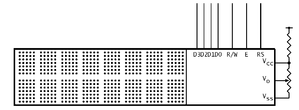
12.8 A typical Liquid Crystal Display, for example the Hitachi LM032L, is shown in Fig. 12.25. Show how you could use a PIC16F84 to give the LCD display an I2C interface.
Fig. 12.25 A LCD display.

![tmp9269_thumb222[2][2][2][2] tmp9269_thumb222[2][2][2][2]](http://what-when-how.com/wp-content/uploads/2011/06/tmp9269_thumb2222222_thumb.png)


