Interrupts happen randomly as viewed by the software and thus, unless masked out, may happen at any part of the background software, including in the middle of a subroutine. An ISR foreground routine uses the internal processor registers in the same way as any other software, so conflict over such resources will exist. For example, the background program could just be testing an object when an interrupt occurs. The Skip instruction which follows the test could be dependent on, say, the state of the Zero flag in the Status register. However, the ISR will in all probability alter Z and thus on return the background program will execute the skip, oblivious of the fact that execution has been transferred in the interregnum. Any change to Z would cause an erroneous branch in the background program. Trying to debug this sort of problem is virtually impossible because the effect of such an interrupt is sporadic as the particular bug depends on the interrupt occurring at just this wrong time and wrong place – something it may do perhaps once a week – and thus is difficult to reproduce.
Another example is illustrated in the polling listing.Here on entry to the ISR, bit RP0 of the STATUS register was set to allow access to Bank 1 SPRs. This was necessary as the EEP-ROM control registers only appear in this bank, whilst both the STATUS and INTCON SPRs are shadowed in both banks. At the exit point, RP0 is cleared to move back to Bank0. However, this assumes that the background program was in Bank0 when interrupted. Clearly this is erroneous if an interrupt occurs during an access to Bank 1.
All but the most elementary ISR will need to, at the very least, save the STATUS and Working registers. Generally the programmer sets aside two File registers as temporary storage and for no other use. Traditionally such locations are named with a leading underscore to show that they are used for system purposes and are not to be tampered with by the User’s program. In Program 7.1 File 1Ch and File 1Dh are labelled _work and _status to conform to this convention.
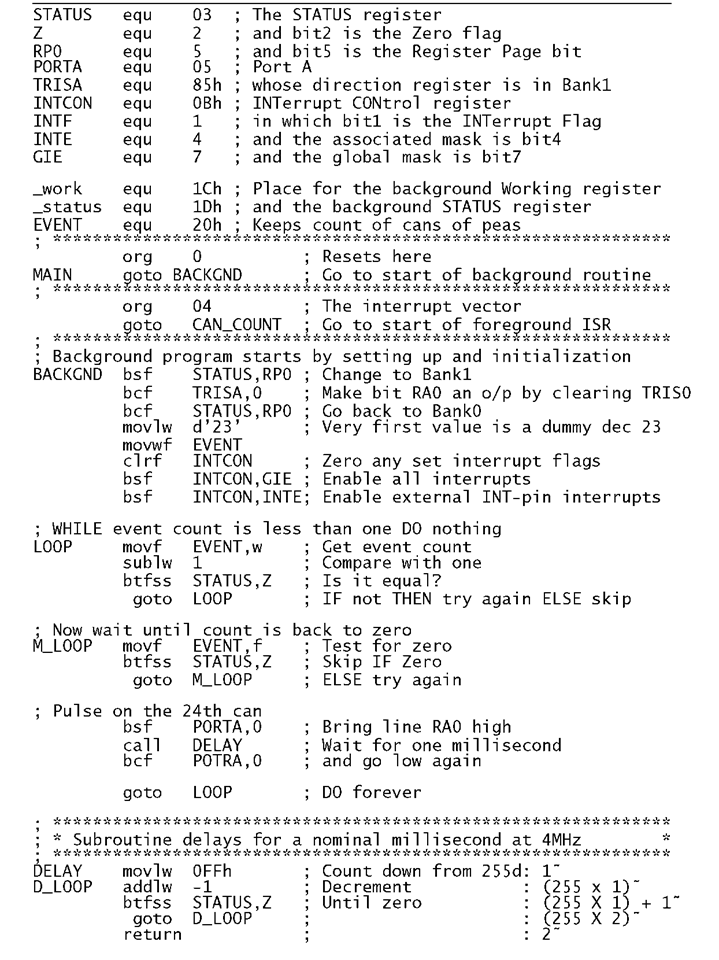
Program 7.1 Background program for the pea canning packer.
Taking as a simple example, consider a conveyer belt in a pea-canning factory. As part of the automatic packing system, a photocell generates a single short pulse for each passing can. The packing machine requires a nominal 1 ms high-going pulse _/ ^ after each batch of 24 cans passes the photocell. Using a PIC16F84 with the photocell sensor connected to the INT pin and the PortA’s pin0 (RA0) driving the packing machine, design both the background and foreground software. Assume that the PIC is being clocked using a 4 MHz crystal.
A suitable background routine is shown in Program 7.1. There are three distinct phases in the code.
Initialization
This phase begins just after the Interrupt vector at 004h. The PIC always resets to the first instruction in the Program store, i.e. 00h, the Reset vector. The first instruction is simply goto BACKGND where BACKGND is the instruction at 005h. Notice how the org directive is used to place this label at 005 h.
As interrupts are automatically disabled on reset, the various File registers and ports are normally set to their initial value at the beginning of the background program before interrupts are enabled. This eliminates the possibility of servicing an interrupt before the initialization code has been completed. The initialization schedule is:
1. All parallel port lines are configured as inputs on reset. To change Port A bit0 to an output, the associated bit in the TRISA SPR must be cleared.
2. The file register used by the ISR to hold the photocell pulse count is set to an initial value of 23. When the first can passes the sensor, the ISR will set this back to zero thinking that 24 cans have now passed.
3. Clearing all bits in the INTCON register clears all interrupt flags that may have been set since reset. This is important as such flags may be set irrespective of the state of the associated mask bits. Setting the Global Interrupt Enable mask bit now enables the interrupt system and specifically setting INTE enables interrupts from the INT pin.
Main routine
The core of the background software repetitively checks the state of the EVENT file register, which is incremented behind the scenes in the ISR. Initially it waits until EVENT passes a count of one. It then checks for a subsequent zero, which occurs when the ISR detects the first can following event 23. That is the count rolling over 22 — 23 — 0. When a zero is detected RA0 is set high, a 1 ms delay subroutine is called, and then RA0 is brought low again.
The sequence is then repeated indefinitely. The initial wait until EVENT is one ensures a ratchet action, with only one outcome _/ ^ for each zero count in EVENT.
Delay subroutine
The delay subroutine immediately follows the endless loop main routine. The hold off is implemented by decrementing from FFh to zero, with W holding the count. This takes 1026 cycles including the launching call, which at 1 ^s per cycle is nominally 1 ms.2
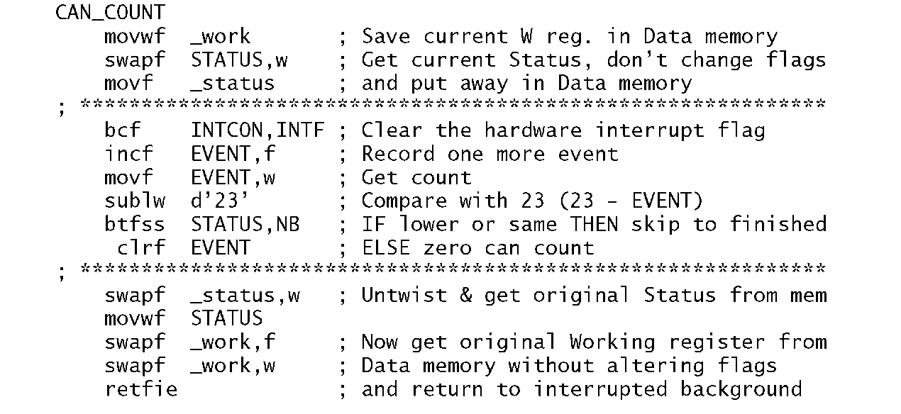
Program 7.2 Event counting foreground software.
When an interrupt occurs the PIC always executes the instruction located at 004h, the Interrupt vector. We see from phase 1 of the background program that this causes execution to transfer to the instruction labelled CAN_COUNT, the first instruction in Program 7.2; that is Interrupt ^ 004h – CAN_COUNT.
The foreground program, or interrupt service routine, can also be divided into three phases.
Context switching
Both the Working and Status register are saved in the Data store. Firstly, W is copied out to _work. Fortunately movwf does not alter any of the status flags, so the state of STATUS is is still that of the interrupted background program.
Saving this STATUS register is more difficult. The obvious approach is to copy it into W and then out to _status. However, the movf instruction alters the Z flag. Instead, we use swapf to copy the datum into W. swapf does not affect the flags but does of course interchange the top and bottom halves of the byte. However, we can untwist them on restoration.
This process of saving and restoring the state of internal registers (this internal state is called the context) on entry and exit is known as context switching. Of course care must be taken that the ISR does not use these locations in Data memory for any other purpose.
Core function
The interrupt flag, INTF in INTCON, is cleared to ensure that on return to the background program another interrupt request is not immediately auctioned…indefinitely. In situations where there is more than one source of interrupts, the various interrupt flags would be polled at this stage of the program.There would then be several core routines, each of which would commence by clearing the appropriate interrupt flag.
The functional sector of the core function simply increments the datum EVENT. This is then checked against decimal 23. If it is higher then EVENT is zeroed. The background program looks for this zero as a sign that 24 cans have passed.
Restoring the context
The exit process first restored the original state of the Status register by swapping out of memory into W. This cancels the original swapf which was used to save the Status register on entry to the ISR. It is then copied from W into STATUS.
Finally, the Working register has to be restored from Data memory. This process must not alter the newly restored STATUS flag settings. Thus swapf is used twice; the first to twist the nybbles out in memory and the second to copy the datum into W and to untwist in the process. The final exit instruction retfie does not alter the flag state.
Although our example showed a context change involving STATUS and W, other SPRs can be saved in the same way. For example, if the File Select Register is used by both background and foreground routines then it should be saved and retrieved at the beginning and end of the ISR – see Example 7.4. In general, if the ISR alters any SPR then its original state should be restored on exit. In all cases W needs to be saved first, as it is used as an intermediary for the other transfers, and similarly restored last.
In common with all interrupt-driven systems, special care has to be taken where multiple sources of interrupt are being handled. As an example, consider a certain system receiving interrupt requests from the Timer at, say, 1000 times per second and externally through the INT pin at an irregular rate. If the INT handler takes, say, 4 ms to execute, then on return three Timer requests will have been lost! Some MCUs have interrupt priority logic so that a higher-priority request (the Timer here) will interrupt a lower-priority process (the INT handler). Here the only solution is to ensure that the latter never takes more than 1 ms to execute.3 In situations where interrupts from several sources occur, a worst-case scenario budget of execution times (including latency) and interrupt rates must be made. As some of these parameters are related to external events beyond the control of the processor, this can be a non-trivial exercise.
Another problem which frequently arises is dealing with events where multiple-precision data are monitored and changed by both background and foreground routines. Consider as an example a real-time clock (RTC) which updates four register files holding time in the 4-byte multiple-precision format HOURS:MINUTES:SECONDS:JIFFY, where the JIFFY byte holds tenths of seconds – see Example 7.4. We assume an external 10 Hz oscillator interrupts the PIC ten times per second, and the ISR updates the time-array.
Consider now that this RTC is part of a central heating controller. At 09:00:00:00 hours the water pump is to be toggled from on to off by the background program. One day this has been done and the time is now 09:59:59:09. The background program, which spends most of its time just looking at the time, reads the hours as 09. Getting interested, it is just going to read the minutes when the Jiffy oscillator ‘ticks’. The MCU is interrupted and the RTC now is updated to 10:00:00:00. On return the background program now reads in succession 00, 00, 00. Thinking that it is now 09:00:00:00 it toggles the pump off and thereafter the on and off periods are interchanged indefinitely!
Of course it is bad design practice to use a toggle action; instead the pump should be switched off at 9 am rather than toggled. At least in this latter case the harm would be time limited. In general the interrupt handler should be disabled by clearing the appropriate mask where such multiple-precision data manipulation routines are being executed in the background – see also Example 7.2. Any interrupts occurring during this time will be acknowledged when the mask is set, although events could be missed if the masked-out period is too long.
In conclusion, ISRs are similar to subroutines, but keep in mind the following points:
• The ISR should be terminated by retfie instead of return.
• Any SPRs that are to be altered should be saved on entry and retrieved on exit.
• Parameters cannot be passed to and from the ISR via the Working register. Instead, global variables (data in known memory locations) should be used as required.
• ISRs should be as short as possible, with minimal functionality. This helps in debugging, and helps ensure that other events are not missed.
• Where multiple-byte data objects are being processed by an ISR consideration should be given to disabling the interrupt system during any background access.
Examples
Example 7.1
In a food processing factory, cans of baked beans on a conveyer belt continually pass through a tunnel oven, as shown top of Fig. 7.5, where the contents are sterilized. Photocell detectors are used to sense cans, both entering and leaving the oven. The output of the sensors are logic 1 when the beam is broken.
You are asked to design an interrupt-driven interface for this system, combining the two signals to activate the PIC’s one INT input. A buzzer connected to Port B’s bit RB0 is to be sounded if the number of tins in the oven exceeds four, indicating that a jam has occurred.
Solution
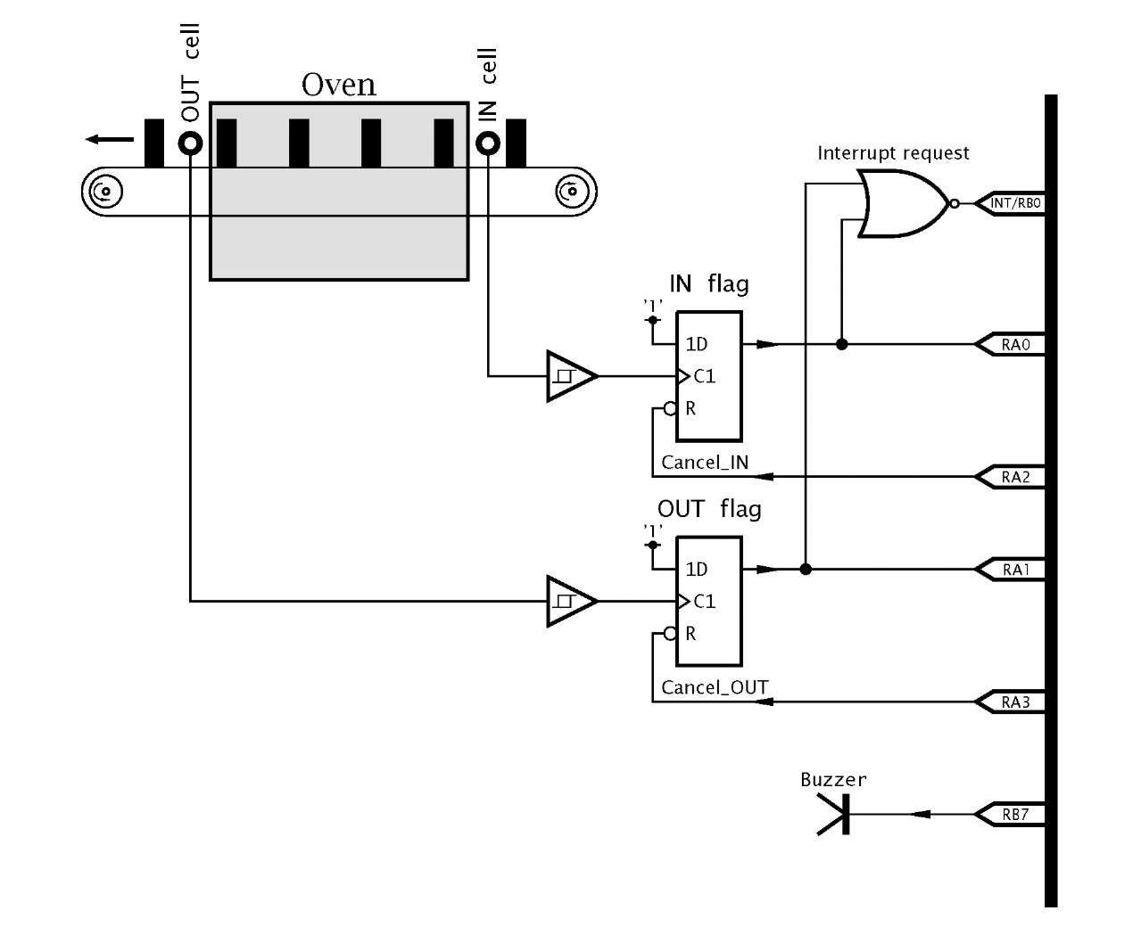
The hardware aspect of this example presents two problems. The first of these involves distinguishing which cell, IN or OUT, generates a request. In Fig. 7.5 each cell clocks an associated D flip flop when the beam is broken. As the D input is permanently tied to logic 1, the clocked flip flop output goes to logic 1. NO Ring both of these interrupt flags together generates a falling edge at the INT pin if any beam is broken.
Both the IN and OUT external flags can be read at Port A pins RA0 and RA1, and this allows the ISR software to distinguish between the two events (can-in and can-out). The appropriate flag can then be reset by toggling the appropriate flip flop reset using two further port lines RA2 and RA3 for Cancel_in and Cancel_out respectively.
One problems remains: If one event follows another before the ISR software has time to reset the appropriate external flip flop, that second event will be missed, as the OR gate will hold INT low. In this situation no further edge can occur and the interrupt system will be permanently disabled! This can be circumvented in software by polling both external flags before exiting the ISR and taking the appropriate action if both bits are not clear.
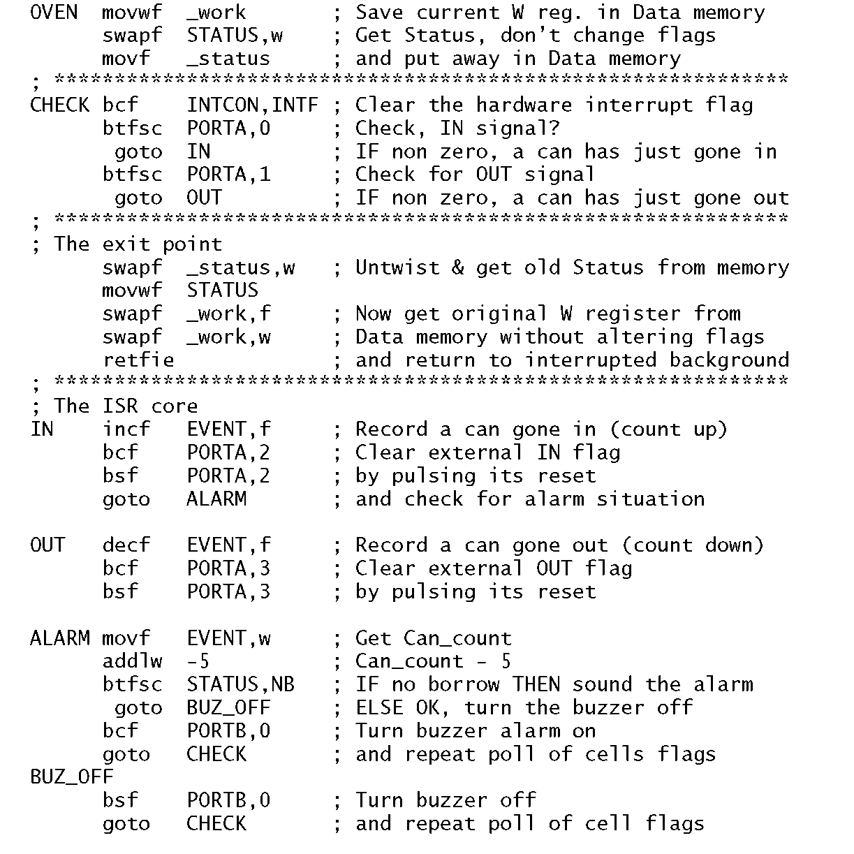
The interrupt service routine for this hardware configuration is given in Program 7.3.
Program 7.3 Oven safety.
1. If pin RA0 is high then a can has broken the IN beam and one is added to the event counter kept in a General-Purpose Register (GPR) in the File store. The external IN flip flop is reset. If the total is greater than four, the buzzer is turned on by bringing RB0 low, otherwise it is turned off. Repeat.
2. If pin RA1 is high then a can has broken the OUT beam and one is taken away from the event counter. This time the external OUT flip flop is reset. Again the total is checked against the boundary of four and the buzzer set to its appropriate state. Repeat.
3. If neither flip flop is set then the ISR exits after restoring the context.
This sequence is repeated whenever actions 1 or 2 have been completed. This ensures that the situation where both beams are broken simultaneously or within a short time window, will be properly serviced.
Fig. 7.5 Oven safety hardware.
The main background program is not shown here. It will be similar to that of Program 7.1 in that the various ports will be set up, the event count file register cleared and interrupts enabled. It is likely that this background program will be in charge of sounding the alarm and other consequent tasks rather than implementing this as part of the ISR, in keeping with the philosophy of reducing the size of the foreground code. In a practical system the background program would probably drive a numeric display showing the aggregrate of cans (four was a ridiculous value, chosen for illustrative purposes only) in the oven. Also some means of resetting to a non-zero value after a jam and some sign in the (unlikely) event of a sub-zero count being computed must be facilitated.
Example 7.2
Sensitive routines in the background software, may be protected by clearing the GIE (General Interrupt Enable) mask and re-enabling it at the conclusion. However, if an interrupt occurs in the middle of the actual instruction clearing GIE (eg. bcf INTCON,GIE) then the interrupt will still be recognized at the instruction’s completion and the ISR entered! What effect would this have on the following protected routine and how could this problem be countered?
Solution
On return from the ISR the retfie instruction will automatically re-enable the interrupt system by setting GIE, so the supposedly protected routine will be left vulnerable to a further interrupt. Any error will be extremely rare as it depends on the conjunction of the following events:
• An interrupt request occurring coincidentally with the clearing of GIE.
• Another interrupt request happening during execution of the protected code.
• The interrupt service routine causing an error in the protected background process.
Such a rare combination would be difficult to reproduce and thus would be virtually impossible to debug.
To avoid this remote possibility of error, the instruction clearing GIE should be followed with a check that it really is clear. For example:
Example 7.3
Interrupt handling anomalies can occur in PICs which do not shadow their general-purpose files registers between banks. We see from Fig. 4.6 that all GPRs in the PIC16F84′s Bank0 are shadowed in Bank 1; for instance File 20h and File A0h are the same. As an opposite example, the PIC16C74 has GPRs between File 20h.. .File 7Fh in Bank0 and between File A0h…File FFh in Bank 1; a total of 192 bytes – as shown in topic B. These register files are bank specific; for instance File 20h is not the same as FileAOh.
The problem arises because the context at the beginning of the ISR will copy W and STATUS into memory in BankO to Bank 3 depending on which bank the processor is in when the background code is interrupted.
If the core of the ISR subsequently switches Bank and then goes back to Bank0 then an error may occur when restoring the context at the end of the ISR if the bank at this point is not that which the processor was in on entry. For example, if the background program was in Bank 1 at the time of interrupt and then moves to Bank0, then the restoration at the termination of the ISR will retrieve the incorrect data from Bank0. Discuss how this problem can be circumvented.


