By : James W Zubrick
Email: j.zubrick@hvcc.edu
Many times you’ll have to heat something. Don’t just reach for the Bunsen burner. That flame you start just may be your own. There are alternate sources you should think of first.
THE STEAM BATH
If one of the components boils below 70 °C and you use a Bunsen burner, you may have a hard time putting out the fire. Use a steam bath!
1. Find a steam tap. It’s like a water tap, only this one dispenses steam (Caution! You can get burned.)
2. Connect tubing to the tap now. It’s going to get awfully hot in use. Make sure you’ve connected a piece that’ll be long enough to reach your steam bath.
3. Don’t connect this tube to the steam bath yet! Just put it into a sink. Because steam lines are usually full of water from condensed steam, drain the lines first, otherwise you’ll waterlog your steam bath.
4. Caution! Slowly open the steam tap. You’ll probably hear bonking and clanging as steam enters the line. Water will come out. It’ll get hotter and may start to spit.
5. Wait until the line is mostly clear of water, then turn off the steam tap. Wait for the tubing to cool.
6. Slowly, carefully, and cautiously, making sure the tube is not hot, connect the tube to the inlet of the steam bath. This is the uppermost connection on the steam bath.
7. Connect another tube to the outlet of the steam bath—the lower connection—and to a drain. Any water that condenses in the bath while you’re using it will drain out.
Usually, steam baths have concentric rings as covers. You can control the “size” of the bath by removing various rings.
Never do this after you’ve started the steam. You will get burned!
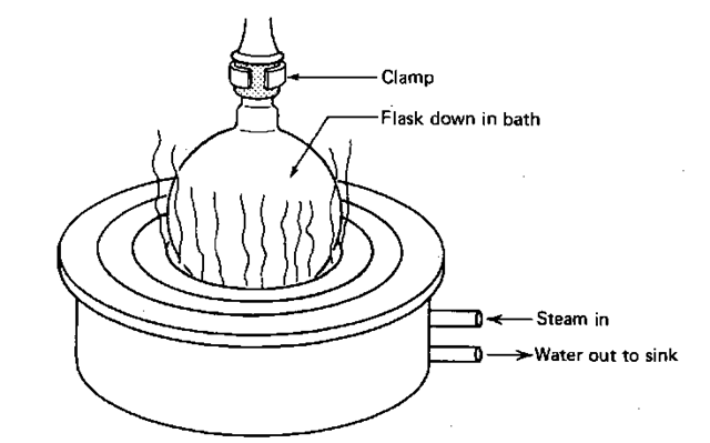
And don’t forget—round-bottom flasks should be about halfway in the bath. Whether you should let steam rise up all around the flask or not appears to be a matter of debate. Lots of steam will certainly steam up the lab and may expose you to corrosion inhibitors (morpholine) in the steam lines. You should not, however, have steam shooting out the sides of the bath, or any other place. (Fig. 57).
THE BUNSEN BURNER
The first time you get the urge to take out a Bunsen burner and light it up, don’t. You may blow yourself up. Please check with your instructor to see if you even need a burner. Once you find out that you can use a burner, assume that the person who used it last didn’t know much about burners, and take some precautions so as not to burn your eyebrows off.
Now Bunsen burners are not the only kind. There are Tirrill burners and Meker burners as well. Some are more fancy than others, but they work pretty much the same. So when I say burner anywhere in the text it could be any of them.
Fig. 57 The steam bath in use.
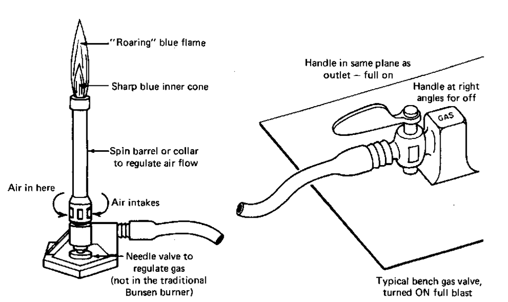
1. Find the needle valve. This is at the base of the burner. Turn it fully clockwise (inward) to stop the flow of gas completely. If your burner doesn’t have a needle valve, it’s a traditional Bunsen burner and the gas flow has to be regulated at the bench stopcock (Fig. 58). This can be dangerous, especially if you have to reach over your apparatus and burner to turn off the gas. Try to get a different model.
2. There is a moveable collar at the base of the burner which controls air flow. For now, see that all the holes are closed (i.e., no air gets in).
3. Connect the burner to the bench stopcock by some tubing and turn the bench valve full on. The bench valve handle should be parallel to the outlet (Fig. 58).
4. Now, slowly open the needle valve. You may be just able to hear some gas escaping. Light the burner. Mind your face! Don’t look down at the burner as you open the valve.
5. You’ll get a wavy yellow flame, something you don’t really want. But at least it’ll light. Now open the air collar a little. The yellow disappears; a blue flame forms. This is what you want.
Fig. 58 More than you may care to know about burners.
6. Now, adjust the needle valve and collar (the adjustments play off each other) for a steady blue flame.
Burner Hints
1. Air does not burn. You must wait until the gas has pushed the air out of the connecting tubing. Otherwise, you might conclude that none of the burners in the lab work. Patience, please.
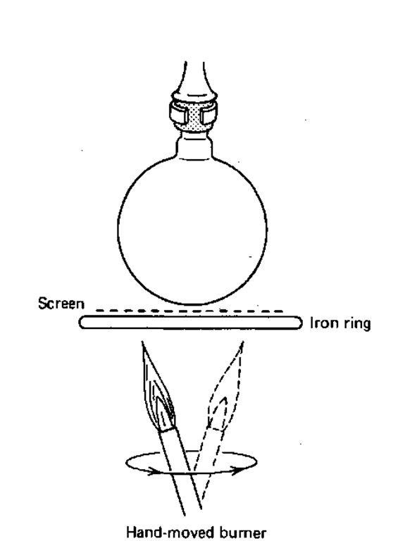
2. When you set up the distillation or reflux, don’t waste a lot of time raising and lowering the entire setup so the burner will fit. This is nonsense. Move the burner! Tilt it! (See Fig. 59). If you leave the burner motionless under the flask, you may scorch the compound and your precious product can become a “dark intractable material.”
Fig. 59 Don’t raise the flask, lower the burner.
3. Placing a wire gauze between the flame and the flask spreads out the heat evenly. Even so, the burner may have to be moved around. Hot spots can cause star cracks to appear in the flask (see Chapter 4, “Round-Bottom Flasks”).
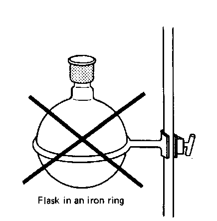
4. Never place the flask in the ring without a screen (Fig. 60). The iron ring heats up faster than the flask and the flask cracks in the nicest line around it you’ve ever seen. The bottom falls off and the material is all over your shoes.
THE HEATING MANTLE
A very nice source of heat, the heating mantle takes some special equipment and finesse.
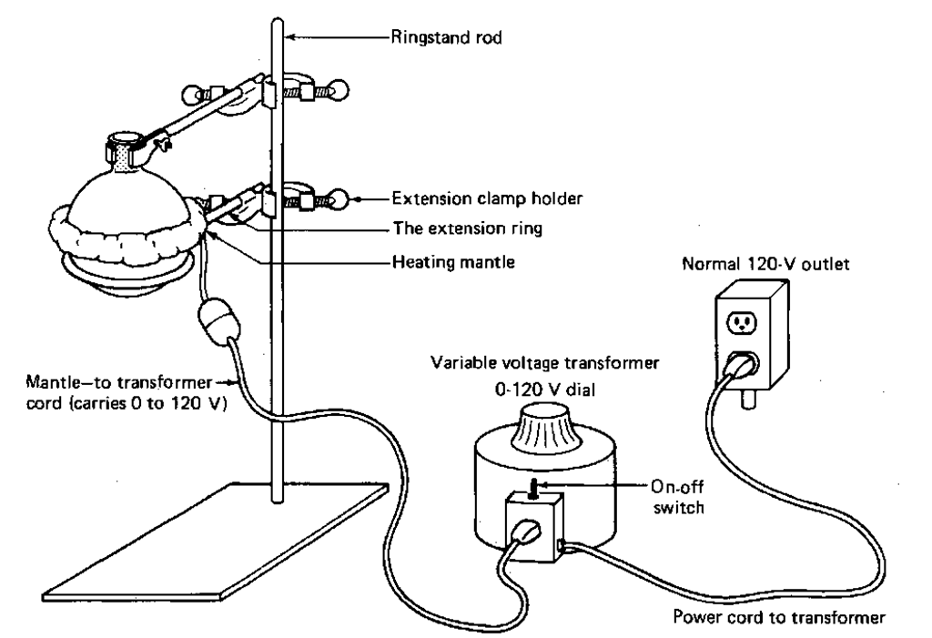
1. Variable voltage transformer. The transformer takes the quite lethal 120 V from the wall socket and can change it to an equally dangerous 0 to 120 V, depending on the setting on the dial. Unlike temperature settings on a Mel-Temp, on a transformer 0 means 0 V, 20 means 20 V, and so on. I like to start at 0 V and work my way up. Depending on how much heat you want, values from 40 to 70 seem to be good places to start.
Fig. 60 Flask in the iron ring.
Also, you’ll need a cord that can plug into both the transformer and the heating mantle.
2. The traditional fiberglass heating mantle. An electric heater wrapped in fiberglass insulation and cloth that looks vaguely like a catcher’s mitt (Fig. 61).
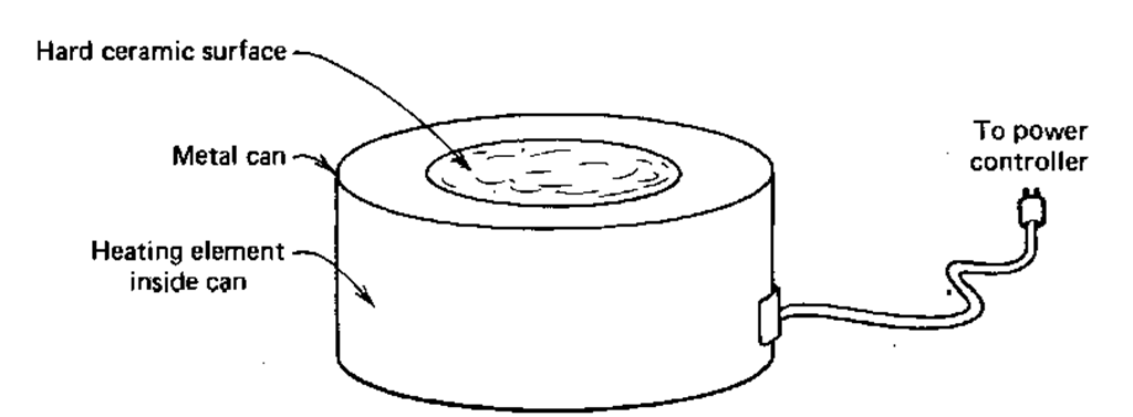
3. The Thermowell heating mantle. You can think of the Thermowell heating mantle as the fiberglass heating mantle in a can. In addition, there is a hard ceramic shell that your flask fits into (Fig. 62). Besides just being more mechanically sound, it’ll help stop corrosive liquids from damaging the heating element if your flask cracks while you’re heating it.
4. Things not to do
a. Don’t ever plug the mantle directly onto the wall socket! I know, the curved prongs on the mantle connection won’t fit, but the straight prongs on the adapter cord will. Always use a variable voltage transformer and start with the transformer set to zero.
b. Don’t use too small a mantle. The only cure for this is to get one that fits properly. The poor contact between the mantle and the glass doesn’t transfer heat readily and the mantle burns out.
c. Don’t use too large a mantle. The only good cure for this is to get one that fits properly. An acceptable fix is to fill the mantle with sand, after the flask is in, but before you turn the voltage on. Otherwise, the mantle will burn out.
HINT. When you set up a heating mantle to heat any flask, usually for distillation or reflux, put the mantle on an iron ring and keep it clamped a few inches above the desktop (Fig. 61). Then clamp the flask at the neck, in case you have to remove the heat quickly. You can just unscrew the lower clamp and drop the mantle and iron ring.
PROPORTIONAL HEATERS AND STEPLESS CONTROLLERS
In all these cases of heating liquids for distillation or reflux, we really control the electric power, not the heat or temperature directly. Power is applied to the heating elements, they warm up, yet the final temperature is determined by the heat loss to the room, the air, and, most important, the flask you’re heating. There are several types of electric power controls
Fig. 61 Round-bottom flask and mantle ready to go.
1. The variable voltage transformer. We’ve discussed this just previously. Let me briefly restate the case: Set the transformer to 50 on the 0 -100 dial and you get 50% of the line voltage, all the time, night and day, rain or shine.
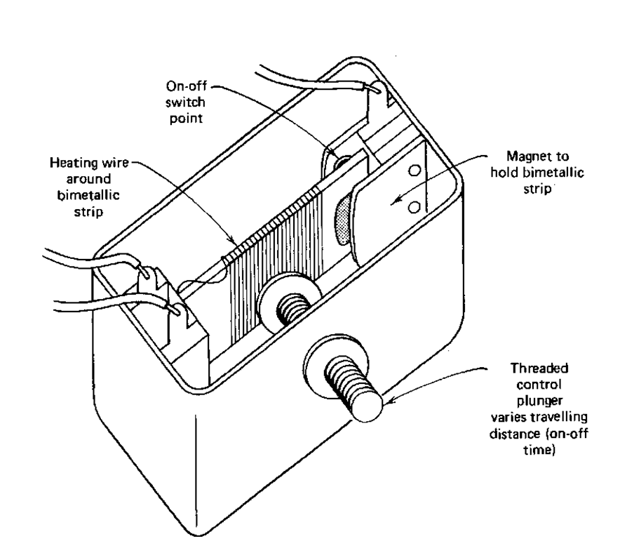
2. The mechanical stepless controller. This appears to be the inexpensive replacement for the variable voltage transformer. Inside one model there’s a small heating wire wound around a bimetal strip with a magnet at one end (Fig. 63). A plunger connected to the dial on the front panel changes the distance between the magnet and a metal plate. With a heating mantle attached, when you turn the device on, current goes through the small heating wire and the mantle. The mantle is now on full blast (120V out of 120V from the electric wall socket)! As the small heating wire warms the bimetal strip, the strip expands, distorts, and finally pulls the magnet from its metal plate, opening the circuit. The mantle now cools rapidly (0V out of 120V from the wall socket), along with the bimetal strip. Eventually, the strip cools enough to let the magnet get close to that metal plate, and—CLICK—everything’s on full tilt again.
Fig. 62 A Thermowell heating mantle.
Fig. 63 Inside a mechanical stepless controller.
The front panel control varies the duty cycle, the time the controller is full on, to the time the controller is full off. If the flask, contents, and heating mantle are substantial, it takes a long time for them to warm up and cool down. A setup like that would have a large thermal lag. With small setups (approx. 50 ml. or so), there is a small thermal lag and very wild temperature fluctuations can occur. Also, operating a heating mantle this way is just like repeatedly plugging and unplugging it directly into the wall socket. There are not many devices that easily take that kind of treatment.
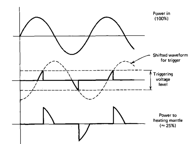
3. The electronic stepless controller. Would you believe a light dimmer? The electronic controller has a triac, a semiconductor device, that lets fractions of the a.c. power cycle through to the heating mantle. The a.c. power varies like a sine wave, from 0 to 120V from one peak to the next. At a setting of 25%, the triac remains off during much of the a.c. cycle, finally turning on when the time is right (Fig. 64). Although the triac does turn “full-off and full-on,” it does so at times so carefully controlled, that the mantle never sees full line power (unless you deliberately set it there).
Fig. 64 Light dimmer and heating mantle triac power control.
