Synchrotron-radiation computed laminography (SRCL) allows for imaging at high resolution 1 ^m) and in three dimensions objects that are thin (~ 1 mm) but extended laterally in two dimensions. This represents a major advantage over computed tomography in terms of loading conditions that can typically only investigate samples elongated in one direction. Here SRCL is used to observe ductile crack initiation and propagation in high strength aluminium alloy sheet for aerospace applications. Several load steps are applied and permit us to follow the changes of damage and crack path. An attempt is made to measure strains via a digital volume correlation technique.
Introduction
Fracture resistance and toughness are critical design criteria for thin sheet materials in aerospace applications and require in-depth understanding of the underlying physical mechanisms to enhance material performance [1]. In the past 2D observation techniques and SEM post mortem fractography have mainly been used to assess fracture mechanisms [2] Synchrotron tomography is increasingly used to assess fracture mechanisms by observing arrested cracks at the initiation [3] and propagation [4] stages. Unprecedented insights into void growth and also intergranular ductile fracture could be gained [5]. In-situ ductile crack growth has been observed [6] via in situ loading of a 2024 aluminium alloy sample with a 1.3 mm x 1.0 mm cross section that permitted to confirm fracture mechanics models. The sample geometry had however dimensions that were far from engineering conditions. With the progress made with synchrotron laminography there is a clear opportunity to observe the damage mechanisms during crack propagation in advanced engineering materials [7], which allows for unprecedented insights into damage mechanisms for sample geometries that can reproduce stress states similar to those experienced in service. In situ loading of a notched sample fracture mechanisms in carbon fibre-epoxy laminates provided insights into delamination processes. This technique is applied in the present study to assess ductile fracture initiation and propagation in a ductile 2XXX alloy for aerospace applications.
With the recent progress in digital volume correlation (DVC) it has become possible to measure strains in 3 dimensions thanks to natural markers / speckle caused by attenuation differences between phases present in the material [8]. DVC has successfully been performed on tomography data of fatigue crack propagation in nodular cast iron. An attempt is made in the present work to apply this technique to in situ synchrotron laminography data to assess the feasibility of the measurement, to obtain insights into strain / damage relationships, and to validate models [9].
Experimental
For the experiment a commercial ductile 2139 Al-Cu alloy in T3 condition for aerospace application has been machined symmetrically from 3.2 mm to 1 mm thickness. Testing has been performed in the T(long transverse)-L(rolling direction) configuration. The material exhibits an initial void volume fraction of ~ 0.3%. For further details on material microstructure and mechanical properties the reader is referred to [3,4]. The sample geometry shown in figure 1a has been used. The notch has been machined via electron discharge (EDMC) machining resulting in a notch diameter close to the EDMC wire diameter of 0.3 mm. The loading has been achieved via a displacement-controlled wedging device that prescribes a specimen crack mouth opening displacement (CMOD) similar to the one used in [7] (see Figure 1).
Figure 1: In situ loading device and 1 mm thick notched sample
An anti-buckling device was used to hamper the sample from significant buckling and out-of-plane motion. The entire rig was mounted in a dedicated plate that has been removed from the SRCL disc for every loading step. The loading has been applied via stepwise opening of the wedge. Before every loading step a scan has been performed. The scanned regions of interest (ROI) have been moved with the propagating crack to image its tip and the damaged material ahead of the notch / crack tip. Twenty scans have been carried out but only results from 6 scans will be shown hereafter.
Laminography is an alternative approach to standard tomography imaging that overcomes the aforementioned sample size / shape problems. The technique is fundamentally similar to tomography except that the sample is imaged at an inclined angle relative to the beam [7]. Previous laminography work at ESRF has yielded very satisfactory results [10]. The further development of the method exploiting propagation-based phase-contrast imaging [11] opens the way for new applications related to weakly absorbing / weakly contrasted structures [12,13].
Imaging was performed on beamline ID19 at ESRF using a monochromatic X-ray beam for an energy of 25 keV. Volumes were reconstructed using an in-house software from 1500 angularly equidistant radiographs; the exposure time of each projection was 250 ms. Due to the experimental set-up the sample to detector distance was 70 mm leading to strong phase contrast. The scanned volume was ~ 1mm3 with a voxel size of 0.7 ^m. For 3D void representation a simple grey value threshold has been used to segment voids; a VTK software rendering is used for the 3D image.
Results and discussion
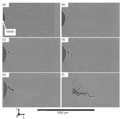
Figure 2 shows 2D sections of laminography data at different openings (CMOD). The section is taken at mid-specimen thickness for every scan. In figure 2a the machined notch can be observed. Initial porosity can clearly be seen in black, intermetallics in white and the aluminium matrix in analogy observations of this or similar material via tomography [3-5]. White edges around porosities are attributed to strong phase contrast. Some ring artefacts can be seen. Figures 2b-f show the change of damage that can clearly be observed. The feasibility of the in-situ experiment is proven, namely, SRCLaminography allows for unprecedented observation of ductile crack initiation and propagation in industrial grade materials at realistic length scales compared to engineering applications.
Substantial void growth can be seen ~ 50^m ahead of the notch (figure 2b). The coalescence of the two voids can be seen in figure 2c. The narrow coalescence band is oriented ~ 45 ° with respect to the loading direction. This result shows that crack initiation does not start immediately from the notch but somewhat (50 ^m in this case) ahead of the notch. At a CMOD of 1.875 mm coalescence of the crack with the notch and further crack propagation in propagation direction occurs. It can be seen that both large voids have changed shape in this coalescence step with the notch. The crack plane orientation is not normal to the loading direction but inclined. The coalescence mechanisms appear to occur in shear bands that is consistent with findings made on the sample surface and theoretical considerations [14]. Figure 2f shows the crack at CMOD = 2.375 mm, which has propagated and reached a length of ~ 1mm. The void growth ahead of the propagating crack appears substantially less than at crack initiation.
The 2 dimensional representation may only be adequate and show the same voids and particles for the mid-thickness plane. This plane can be assumed to show the change of the same microstructural features at least during the first loading steps. Once the fracture process becomes asymmetric, e.g. due to slant fracture, one plane will not show the same material features for all loading steps.
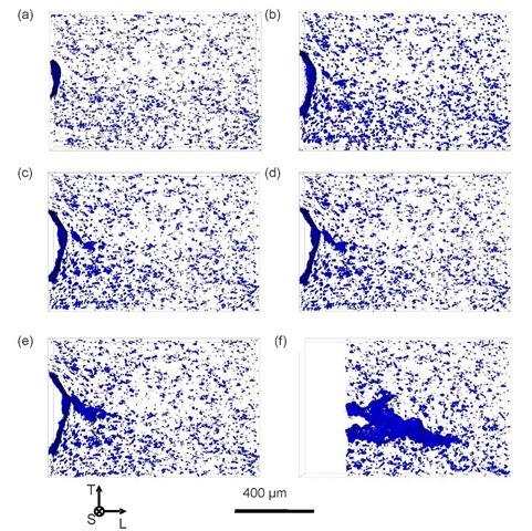
As laminography provides 3D data it offers the opportunity to show the change of voids in 3D. This is shown in figure 3 where voids from a 105 ^m thick slice symmetric to the mid plane are represented. Only voids are made visible here. (The thickness is not corrected for transverse contraction as the latter is inhomogeneous in the plane). The same loading steps as in figure 2 are shown. Between the initial microstructure (figure 3a) and the deformed voids it can be seen that void growth takes place around the entire notch. A lot more voids can be observed than for the 2D representation. The void growth and orientation appear highly directional. The voids change orientation around the notch during loading and orient themselves tangential to the notch circumference.
The 3D representation also confirms the crack initiation from the interior of the material. However, in figure 3d it can be seen that the two large voids are already connected with the notch that was not discernable on the 2D sections at the mid-plane.
Figure 2: 2D section at sheet mid-thickness from in-situ SRCLaminography data for a) CMOD = 0.5 mm b) CMOD = 1.5 mm c) CMOD = 1.625 mm d) CMOD = 1.75 mm e) CMOD = 1.875 mm f) CMOD = 2.375 mm
Figure 3. 3D representation of voids and the crack in a numerically cut 105 ^m thick slice at sample centre for a) CMOD = 0.5mm b) CMOD = 1.5 mm c) CMOD = 1.625 mm d) CMOD = 1.75 mm e) CMOD = 1.875 mm f) CMOD = 2.375mm
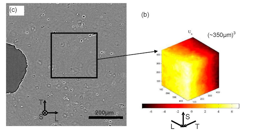
Figure 4 shows the displacement field measured by DVC with same the code as that used in [8] on the present laminography data by registering 2 volumes located in the squared box indicated in figure 4a. The reconstructed volumes corresponding to CMOD = 0.5 mm and CMOD = 0.625mm are compared. The volume of the compared cubes is taken symmetrically to the sheet mid-thickness. The measured displacement field is qualitatively correct, namely, an expansion in T direction is detected that is consistent with the loading along the same direction. This preliminary result prompts us to continue the analysis for further loading steps, and to derive the strain fields. These measurements may then open the possibility to obtain insights into deformation field and strain localization mechanisms leading to crack bifurcation. A relationship between measurements of void growth at different levels of stress triaxiality and strain may become accessible in that case.
Figure 4: a) 2D section of the scan when CMOD = 0.5 mm indicating the region of interest for DVC b) Measured displacement field between CMOD = 0.5mm and 0.625 mm, colorbar indicating displacements in T direction expressed in voxels
Conclusion
Ductile fracture of thin (but laterally extended) sheet aluminium alloy has been successfully observed for the first time thanks to the use of Synchrotron Radiation Laminography. The artefacts introduced by this technique are small enough to clearly observe ductile fracture mechanisms involving void nucleation, growth and coalescence in conditions that are realistic for engineering applications. Damage can easily be extracted via simple grey value thresholding. Fracture revealed to initiate ahead of the notch and only after substantial void growth to join the notch. The crack path is not normal to the loading direction but inclined. The obtained data can be used for in-situ void growth measurements. An initial attempt to perform digital volume correlation on the laminography data led to qualitatively successful measurements of the displacement field, which encourages further strain analyses.


