Abstract
The use of polymeric and metallic foam sandwich panels in naval, aerospace, railway and automotive constructions is rapidly growing in the recent years because of technological improvements in manufacturing processes. However, it is still difficult to establish a direct relationship between the mechanical properties possessed by the panel and the specific manufacturing process. Mechanisms behind panel deformation, crack growth, fracture initiation and propagation still are not completely understood and therefore are intensively studied. In particular, structural behavior under compression is a critical issue also in view of the lack of official standards on foam core sandwich panels. This work aims at studying mechanical properties of high density polyethylene foam core sandwich panels produced by rotational molding. These panels can be built without using adhesives as the polyethylene foam grows inside mold and then adheres to facesheets while material still is at high temperature. In the present study, polyethylene foam panels of different thickness are tested under edgewise compression loading. The resulting out-of-plane deformation is then monitored in detail with a projection moire setup including two projectors and one camera.
INTRODUCTION
Foam core sandwich panels, made up of two polyethylene skins separated by a lightweight polyethylene foam, may represent an excellent solution to many design problems in the automotive field [1]. Mechanical properties of these panels can be improved by properly selecting the manufacturing process although it is very difficult to establish a direct relationship between mechanical properties and manufacturing parameters. Amongst manufacturing techniques, rotational molding is an innovative process which makes it possible to build the entire sandwich component within just one step, thus obtaining a better adhesion and improving the continuity between skins and core. It is expected that the above mentioned technology will allow manufacturing time to be reduced as well as mechanical characteristics of the panel to be improved.
Compressive strength, flexural properties and impact behavior are important issues in the mechanical characterization of foam core sandwich structures [2-4]. However, mechanisms behind panel deformation, crack growth, fracture initiation and propagation still are not completely understood and therefore are intensively studied. In particular, structural behavior under compression probably is the most critical issue also in view of the lack of official standards on foam core sandwich panels. For example, Casavola et al. [5] have recently carried out a detailed investigation on the mechanical behavior of aluminum foam sandwich panels subject to flatwise compression (i.e. in the direction orthogonal to facesheets) or edgewise compression (in the direction parallel to facesheets). They found that the foam contributes significantly to the ultimate compressive strength of the panel as long as aluminum skins remain bonded to the core. Flatwise compression strength increases with specimen size. Structural response is sensitive to the presence of voids or imperfections in the foam.
Since sandwich foam panels are thin-walled structures, their structural response under compression may be driven by buckling. The onset of buckling becomes more probable as the foam core structure is less regular: that is, when there are voids or irregularities in the foam structure. Buckling modes are characterized by large out-of-plane displacements and the main concern hence is to measure deflections with a great deal of accuracy.
Fringe projection techniques [6] are naturally suited for the problem of monitoring large out-of-plane displacements of thin walled structures. The projected lines are modulated by the specimen surface: if lines are projected onto a curved surface, curvature and frequency of these lines will change; if, instead, lines are projected onto a plane, they remain straight and parallel but their spacing may change. In shadow moire, fringes form because the projected grating modulated by the object surface is superimposed to the grating itself located in the vicinity of the specimen. Therefore, the sensor "sees" a pattern a fringes that represents loci of equal parallax. The parallax is in turn related to the surface height Z(x,y), expressed as the distance from the reference plane. In projection moire, the image of the modulated pattern of lines is recorded and digitally compared with the image of the same grating projected onto a flat surface called reference plane. By subtracting the two images recorded for the curved surface and for the reference plane, it is possible to obtain the level lines (in reality, the loci of equal parallax) of the surface: that is, to know the distribution of height Z(x,y) for each point P(x,y) of the deformed object. Whilst moire fringes are directly sensed in the case of shadow moire, projection moire fringes are generated via digital subtraction of images.
In the case of large structures, the collimated illumination can be replaced by a central projection and some correction model must be introduced to account for the divergence of the illumination beam. Fleming et al. [7-9] demonstrated that projection moire can accurately measure displacements of models submitted to aerodynamic loads; projection moire and photogrammetry were found to be substantially competitive. Featherston and Lester [10] monitored post-buckling behavior of thin panels with projection moire. Other examples of experimental buckling analysis of thin-walled stiffened panels are documented in Ref. [11].
The most recent development in projection moire is the four-projector setup proposed by Sciammarella and his coworkers [12,13]. A simplified version of that optical setup employing only two projectors and one camera is utilized in this research in order to characterize the compressive behavior of polyethylene foam core sandwich panels subject to edgewise compression tests.
EDGEWISE COMPRESSION TESTS
In edgewise compression tests the load acting on the specimen is directed parallel to facesheets. The purpose of the test is twofold: (i) to analyze the mechanical behavior of the skins, that are much thinner than the specimen core; (ii) to analyze the core contribution to the compression resistance. In this study, experimental tests were carried out following partially ASTM standards [14] that supply indications for generic sandwich structures.
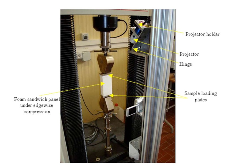
Specimens were cut from sandwich foam panels: each specimen is 150 mm long and 70 cm wide while thickness may either be 30 mm or 40 mm. A total of 5 specimens (two of thickness 30 mm, and 3 of thickness 40 mm; thickness of skin is about 3 mm) were tested. The nominal dimensions of each specimen were carefully checked before executing the compression tests. This was done in purpose to precisely compute stress. The average density of the 30 mm thick specimens is 222.84 kg/m3 while the average density of the 40 mm thick specimens is 149.34 kg/m3. Compression tests were conducted on an electromechanical testing machine (MTS Alliance RT/30). Special fixtures were designed in order to clamp the specimen in the testing machine. Figure 1 shows the loading frame. Load and displacement signals as well as strain gage signals (two strain gage rosettes were bonded on the skins with 3 mm gage length and 120Q electrical resistance; the central grid b was aligned with the longitudinal axis of the specimen) were acquired by System 5000, Micro Measurements, USA.
Figure 1. Loading frame utilized for the edgewise compression tests
The edgewise compression loading produced a huge deformation in the sample (see Figure 2). Facesheets underwent buckling because of their detachment from the core. Significant out-of-plane displacements are associated to this phenomenon which initiated where local thickness is very small or where foam is irregularly distributed in the core: this caused facesheet delamination from core (see detailed view in Figure 2). However, samples recovered almost completely their original geometry upon removal of the applied load in spite of the fact that end-shortening vales of up to 10 mm were observed (see Figure 3).
Figure 2. Deformation pattern typically observed by the foam core sandwich panel in the edgewise compression test
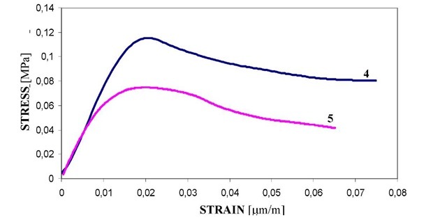
Stress-strain curves recorded in the experiments are shown in Figures 4 and 5, respectively, for the 40mm and 30mm thick specimens. The stress value was computed as the ratio between the force value sensed by the loading cell and the area of the transverse section of each facesheet. The strain value was computed as AL/L0 where L0 is the initial length of the sample while AL corresponds to the nominal end shortening sensed by the loading frame.
Figure 3. Image of a 40mm thick specimen before (a) and after (b) executing the edgewise compression test; c) Load-displacement curve registered for a 30mm thick specimen
Figure 4. Stress-strain curves recorded for the 40mm thick specimens
Figure 5. Stress-strain curves recorded for the 30mm thick specimens!
Stress-strain curves recorded experimentally always include a pseudo-linear range corresponding to the Hookean behavior. The average values of Young modulus derived from the linear fitting of the o-e curves are listed in Table 1 for all specimens tested in this study. As expected, stiffness increased in the case of thinner panels. Besides the obvious consideration that thick cores must be less stiff than thin cores as the fraction in volume of facesheets decreases and this makes the specimen easier to be deformed by the edgewise compression load, it is to be noted that stress-strain curves are very different even for specimens with the same nominal thickness and a small deviation on average thickness.
Table 1. Values of the mechanical properties possessed by the samples submitted to edgewise compression tests
|
Sample |
Average thickness [mm] |
Young modulus [MPa] |
Specific stiffness (E/p) |
|
1 |
42.11 |
4.16 |
0.030 |
|
2 |
42.15 |
4.07 |
0.030 |
|
3 |
41.96 |
4.29 |
0.030 |
|
4 |
33.97 |
7.15 |
0.032 |
|
5 |
34.27 |
6.36 |
0.028 |
This behavior can be explained with the variations in core structure deriving from the process of fabrication which either results in a different topology of the cells and a different level of compactness of the core. However, the average value of specific stiffness was found to be practically the same for all specimens.
PROJECTION MOIRE MEASUREMENTS
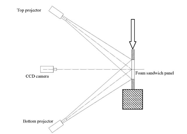
The out-of-plane displacement field experienced by the foam sandwich panels subject to edgewise compression was investigated in detail with the multi-projector moire model developed by Sciammarella et al. [12,13]. As the surface is a tensor entity, the optical setup should always include four projectors. However, if the surface to be measured is curved prevalently with respect to the horizontal axis, like it occurred in the present case, only two projectors can be utilized (Figure 6). The two projectors must be placed symmetrically with respect to the optical axis of the camera and project structured non-collimated light onto the surface of the sample. This allows the ideal condition of projection from infinity to be achieved. By changing the angle 8 formed by the optical axis of the projector with respect to the optical axis of the sensor, and utilizing gratings of different pitch one can obtain different values of sensitivity and thus contour samples with dimensions ranging from few microns to meters.
Figure 6. Schematic of the optical set-up utilized to measure out-of-plane displacements of foam sandwich panels
Two different sets of images are necessary in order to conduct the measurements. The first set is represented by the images of the grating projected onto the surface of a reference plane: the grating is obtained by illuminating the surface with the top side or the bottom side projector. The second set is represented by the images of the grating projected on the surface of the sample obtained in the same way as described above. The first set of images can be recorded and then stored in the computer memory as the system is calibrated. If![]() is the phase of the reference plane obtained by illuminating the plane with the upper projector and ^RP-B(x,y) is the phase of the reference plane obtained illuminating the plane with the lower projector, the phase of the reference plane is
is the phase of the reference plane obtained by illuminating the plane with the upper projector and ^RP-B(x,y) is the phase of the reference plane obtained illuminating the plane with the lower projector, the phase of the reference plane is![]() Similarly, if
Similarly, if![]() , are the phases of the sample obtained by illuminating it with the top and bottom projectors, respectively, the total phase of the sample is
, are the phases of the sample obtained by illuminating it with the top and bottom projectors, respectively, the total phase of the sample is![]()
If AOtot is the total phase determined as![]() of each point of the sample
of each point of the sample
with respect to the reference plane is:
where: m is the magnification andpo is nominal pitch size of the grating. The accuracy of the two-projector moire setup is of the order to some hundreds of sensitivity mpo/2tan 8.
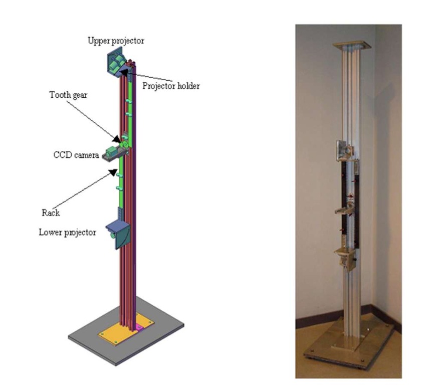
Figure 7. Schematic of the metallic frame realized in order to carry out measurements of out-of-plane displacement
An ad hoc metallic frame was designed and realized to measure out-of-plane displacements with the optical set-up above described. The frame is shown in Figure 7. Three aluminum bars were assembled to guide the movement of the projectors and CCD camera. A tooth gear engages with two racks onto which are fixed the projectors. By utilizing the tooth gear it is possible to place projectors symmetrically with respect to the axis of the CCD camera. The projectors are fixed to the frame through holders that can rotate about an axis of a hinge. A graduated scale reported on the holder allows to give to the projector the exact value of rotation necessary to have its optical axis aligned with the center of the sample. The tooth gear is fixed onto a support including a plate onto which a CCD camera is attached. The two racks as well as the tooth gear can translate along the vertical direction so that panels of different dimensions can be measured on different testing machines. In the present experiments, two LTPR3W/R OEPL 50° diode projectors and a XCL-5000 5 Mega CCD camera were utilized.
The 3D view of the optical setup is shown in Figure 8. Ad hoc fixtures were realized to fix the specimen in the loading frame having no shadows projected onto the surface of the sample. A very thin layer of powder was coated on the specimen to improve the contrast of the projected fringes. The plane containing the sensor of the CCD camera was disposed parallel to the surface of the sample and its center was aligned with the center of the sample under investigation. A preliminary calibration procedure was conducted to determine the size of the pixels of the acquired images. The pitch of the projected gratings po was 127 ^m. Due to the large aperture of the beam emerging from the projectors (the angle of aperture of the beam is 50°) a magnification m=53.33 was obtained. By inclining projectors by 52.5° with respect to the optical axis of the CCD camera a value of sensitivity As equal to 2598 ^m (see Eq. (1)) was obtained.
The compression test was conducted in subsequent steps: the vertical displacement of the cross bar was increased by 0.5 mm per step to give the corresponding end-shortening to the specimen. Images were taken at intervals of 60 seconds. The surface of the unloaded specimen was assumed to be the reference plane.
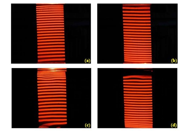
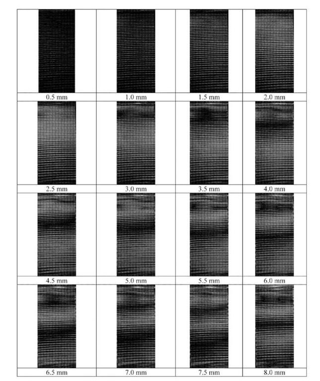
Figure 9 shows the surface of the unloaded sandwich panel (Figures 9a and 9b) and loaded panel (Figures 9c and 9d). The "loaded" configuration corresponds to an axial displacement of 8 mm. It is interesting to observe how projected fringes are approximately parallel before the beginning of the compression test and how they are modulated by the surface of the sample as the axial displacement given to the sample increases. Figure 10 shows the moire fringes formed for each axial displacement investigated. Fringe topology is consistent with the deformations observed in the experimental tests described in Section 2. By analyzing the distribution of spatial frequency of moire fringes it can be observed that the relationship between out-of-plane displacement and end-shortening is highly nonlinear.
Figure 8. Optical setup for measuring out-of-plane displacements
Figure 9. Fringes projected onto the surface of the unloaded sample (a,b) and loaded sample (c,d) by the top projector (a,c) and the bottom projector (b,d).
SUMMARY AND CONCLUSIONS
This study presented an experimental study to evaluate the structural response of polyethylene foam sandwich panels subject to edgewise compression. Two different experimental campaigns were conducted. The first campaign served to analyze the stress-strain curves while the second campaign analyzed in detail the out-of-plane displacement field by means of two-projector moire setup. The experimental analyses carried out in this study are relevant as it is still difficult to establish a direct relationship between mechanical properties of foam sandwich panels and the specific manufacturing process.
Figure 10. Evolution of moire pattern at increasing end shortening


