Because you can do so many things with the OpenGL graphics system, an OpenGL program can be complicated. However, the basic structure of a useful program can be simple: its tasks are to initialize certain states that control how OpenGL renders and to specify objects to be rendered.
Before you look at some OpenGL code, let’s go over a few terms. Rendering, which you’ve already seen used, is the process by which a computer creates images from models. These models, or objects, are constructed from geometric primitives—points, lines, and polygons—that are specified by their vertices.
The final rendered image consists of pixels drawn on the screen; a pixel is the smallest visible element the display hardware can put on the screen. Information about the pixels (for instance, what color they’re supposed to be) is organized in memory into bitplanes. A bitplane is an area of memory that holds one bit of information for every pixel on the screen; the bit might indicate how red a particular pixel is supposed to be, for example. The bitplanes are themselves organized into a framebuffer, which holds all the information that the graphics display needs to control the color and intensity of all the pixels on the screen.
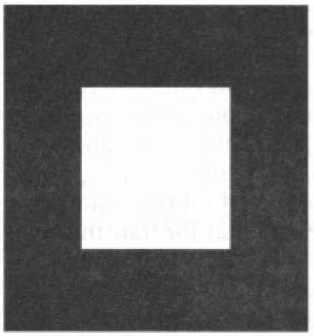
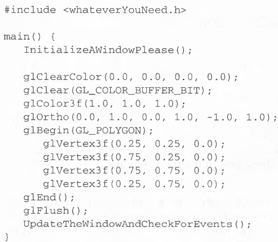
Now look at what an OpenGL program might look like. Example 1-1 renders a white rectangle on a black background, as shown in Figure 1-1.
Figure 1-1 White Rectangle on a Black Background
Example 1-1 Chunk of OpenGL Code
The first line of the main() routine initializes a window on the screen: The InitializeAWindowPleaseQ routine is meant as a placeholder for window- system-specific routines, which are generally not OpenGL calls. The next two lines are OpenGL commands that clear the window to black: glClearColor() establishes what color the window will be cleared to, and glClearO actually clears the window. Once the clearing color is set, the window is cleared to that color whenever glClear() is called. This clearing color can be changed with another call to glClearColor(). Similarly, the glColor3f() command establishes what color to use for drawing objects—in this case, the color is white. All objects drawn after this point use this color, until it’s changed with another call to set the color.
The next OpenGL command used in the program, glOrtho(), specifies the coordinate system OpenGL assumes as it draws the final image and how the image is mapped to the screen. The next calls, which are bracketed by glBegin() and glEnd(), define the object to be drawn—in this example, a polygon with four vertices. The polygon’s "corners" are defined by the glVertex3f() commands. As you might be able to guess from the arguments, which are (x, y, z) coordinates, the polygon is a rectangle on the z = 0 plane.
Finally glFlush() ensures that the drawing commands are actually executed, rather than stored in a buffer awaiting additional OpenGL commands. The UpdateTheWindowAndCheckForEvents() placeholder routine manages the contents of the window and begins event processing.
Actually, this piece of OpenGL code isn’t well structured. You may be asking, "What happens if I try to move or resize the window?” or "Do I need to reset the coordinate system each time I draw the rectangle?". Later in this topic, you will see replacements for both InitializeAWindowPlease() and UpdateTheWindowAndCheckForEvents() that actually work but require restructuring of the code to make it efficient.


