Precise head and shoulders posture measurement
Our new non-invasive head position measurement method was designed for use in neurology to discover relationships between some neurological disorders and postural alignment. The objective was to develop a technique for precise and non-invasive head posture measurement in 3D space. The technique is aimed at determining differences between the anatomical coordinate system and the physical coordinate system with accuracy from one to two degrees for inclination and rotation (Harrison & Wojtowicz, 1996). Pictures or recordings of the head marked on the tragus and the outer eye canthus, see Figure 1, and the shoulders marked on acromions are taken simultaneously by cameras aligned by a laser beam, magnetometers or inertial systems.
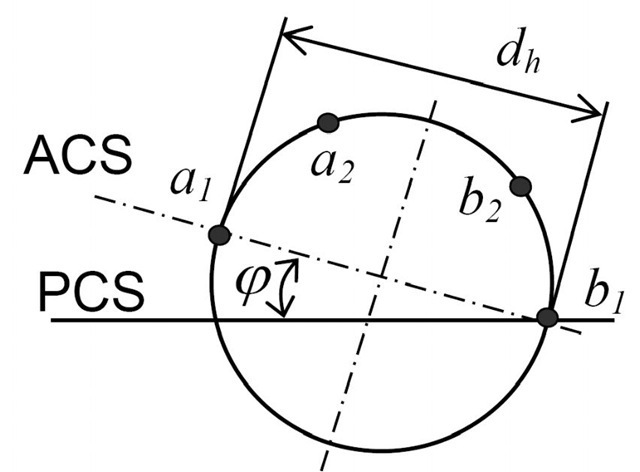
Fig. 2. Geometry used for measuring the head position (top view).
In our recent method for studying only head position (Kutilek & Hozman, 2009), only two cameras are required for determining head positions i.e. anatomical coordinate system in the physical coordinate system. The rotation and inclination of the head is calculated from the difference between the tragus coordinates in the left-profile and right-profile image or eventually in the frontal picture and top view picture of head. The coordinates of the left and right tragus are evaluated by finding the centre of the rounded mark attached to the tragus. After evaluating the coordinates of the tragus in the captured images, the angles of head rotation and inclination are calculated. The images are captured simultaneously, using two cameras, which are calibrated. The adjustment of the camera system defines the position of the head in the instrument coordinate system. The position of the head in the physical coordinate system is determined by special software and the exactly known adjustment of the camera system.
Generally, the angles of rotation and inclination can be determined by vector v and vector u, which represent the coordinates of the points evaluated in the image, see Figure 2. The angle (for example rotation![]() ) is calculated as follows (1):
) is calculated as follows (1):
where
The![]() is the x-axis coordinate and
is the x-axis coordinate and![]() is the y-axis coordinate of the left tragus in the top view image. The
is the y-axis coordinate of the left tragus in the top view image. The![]() is the x-axis coordinate and
is the x-axis coordinate and![]() is the y-axis coordinate of the right tragus in top view image. We can determine the angle of inclination σ in the similar way in the frontal view image. After calculation of the angles in the instrument coordinate system, the angles in physical coordinate system are derived by mathematical transformation.
is the y-axis coordinate of the right tragus in top view image. We can determine the angle of inclination σ in the similar way in the frontal view image. After calculation of the angles in the instrument coordinate system, the angles in physical coordinate system are derived by mathematical transformation.
If we use profile photographs (side shots) and want to evaluate the elevation/ depression of the head in the instrument coordinate system and sagittal plane, it is also a mathematically simple problem. The flexion value is measured relatively as the inclination of the connecting line between the coordinates of tragus and the exterior eye corner. The coordinates are evaluated by finding the centre of the rounded mark attached to the tragus and outer eye canthus of the patient. The angle between the anatomical and physical or instrument horizontal (depends on adjustment of instrument) is determined by the angle between vector v (horizontal vector), here given by the camera position, and vector u, which here represents the coordinates of the points (corresponding to the tragus marker and exterior eye corner marker) evaluated in the image. The angle is calculated as follows (4):
where
![]() is the x-axis coordinate and
is the x-axis coordinate and![]() is the y-axis coordinate of the tragus in the profile image, and
is the y-axis coordinate of the tragus in the profile image, and![]() is the x-axis coordinate and
is the x-axis coordinate and![]() is the y-axis coordinate of the outer eye canthus in the profile image.
is the y-axis coordinate of the outer eye canthus in the profile image.
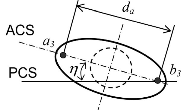
Fig. 3. Geometry used for measuring the shoulder position (top view).
For evaluating shoulder inclination and shoulder rotation, we use a method similar to the method that we use for evaluating head position. Picture of acromions on shoulders is taken by cameras. A medical doctor indicates acromions with marks for easy location of these anatomical points in the pictures. If the clinical investigation is carried out by an experienced medical doctor, it is not necessary to apply coloured marks to the anatomical parts of the body before making an examination using camera system. The software can also determine the angular displacement of the head to the shoulders for rotation, using the formula
where the η is angle of shoulders rotation (Figure 3) and φ is angle of head rotation (Figure 2). The angular displacement of the head to the shoulders for inclination
where the![]() is angle of shoulders inclination and
is angle of shoulders inclination and![]() is angle of head inclination.
is angle of head inclination.
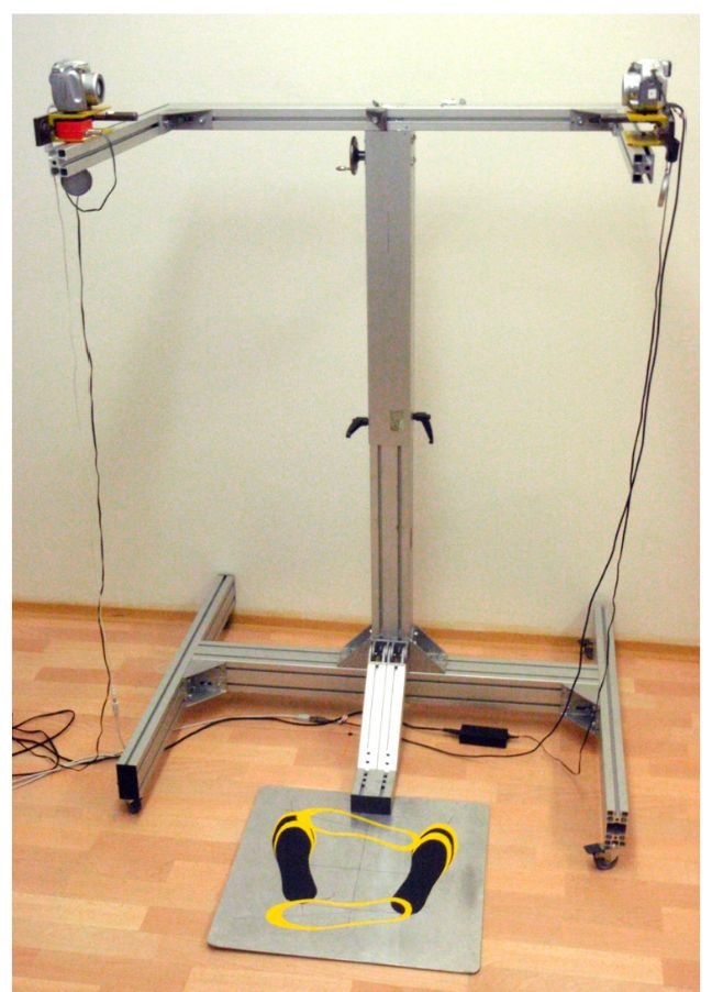
In the way described above, based on identifying anatomical points with the use of two cameras (Figure 4) we can avoid influencing patients while we are measuring the inclination (roll), flexion (pitch) and rotation (yaw) of the head and shoulders.
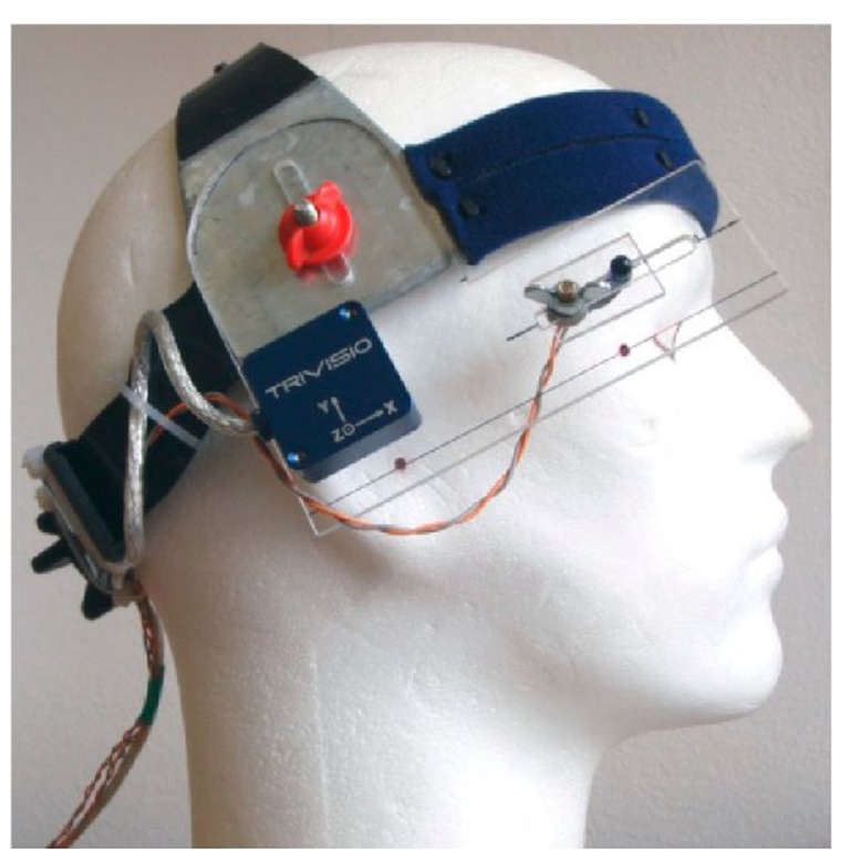
The last proposed system is a combination of camera and gyroscope-accelerometer system. One camera is placed vertically above the patient’s head. The second camera is positioned behind the patient in order not to impede the frontal view of the patient during the examination. Shoulders are marked in 3D space by a two IR diodes. Position of the two anatomical points (acromions) on the shoulders is defined by the two IR diodes. Diodes are placed on patient’s shoulders by the physician before the examination. The position of head’s anatomical coordinate system is defined by a special instrument, see Figure 5. A physician puts the instrument on patient’s head. The physician defines the position of the anatomical axes of the head by a special ruler on the instrument. Position of the head is defined by the two IR light diodes mounted on the instrument and gyroscope-accelerometer system. Rotation and inclination is then determined from the position of two infrared diodes mounted on the instrument and by two cameras. Flexion/extension is determined by accurate gyroscope-accelerometer system made by the company TRIVISIO, which is also part of the special instrument. The proposed special instrument is in Figure 5.
Fig. 4. The two-arm stand with fixed two cameras and laser collimators designed for the precise adjustment of the system.
Fig. 5. Combined inertial system with infrared marker for detecting the position by IR camera system.

![tmpD26_thumb[2] tmpD26_thumb[2]](http://what-when-how.com/wp-content/uploads/2012/05/tmpD26_thumb2_thumb.png)
![tmpD27_thumb[2] tmpD27_thumb[2]](http://what-when-how.com/wp-content/uploads/2012/05/tmpD27_thumb2_thumb.png)
![tmpD36_thumb[2] tmpD36_thumb[2]](http://what-when-how.com/wp-content/uploads/2012/05/tmpD36_thumb2_thumb.png)
![tmpD37_thumb[2] tmpD37_thumb[2]](http://what-when-how.com/wp-content/uploads/2012/05/tmpD37_thumb2_thumb.jpg)


