INTRODUCTION
The mass-strength ratio is of exceptional importance for different applications. Critical parts of various moving vehicles from satellites to aircrafts to cars depend on strength and toughness of the materials they are made of, while strict limitations on the weight of the different components are placed by the launch technology. Single-walled carbon nanotubes (SWNT) present significant potential as the basic material for space applications. The exceptional mechanical properties of SWNTs[1-6] have prompted intensive studies of their composites. These qualities can also be used in a variety of other technologies from automotive to military and medical. However, the present composites have shown only a moderate strength enhancement when compared to other hybrid materials.[7-9] Although substantial advances have been made,[10] the mechanical characteristics of SWNT-doped polymers are noticeably below their highly anticipated potential. Pristine SWNTs are well known for poor solubilization, which leads to phase segregation of composites. Severe structural inhomogeneities result in the premature failure of the hybrid SWNT-polymer materials. The connectivity with and uniform distribution within the matrix are essential structural requirements for the strong SWNT composites.[11-13] Here we show that a new processing approach based on sequential layering of chemically modified nanotubes and polyelectrolytes can greatly diminish the phase segregation and render SWNT composite highly homogeneous. Combined with chemical cross-linking, this processing leads to drastically improved mechanical properties. The tensile strength of the composites is several times higher than that of SWNT composites made via mixing; it approaches values seen for hard ceramics. The universality of the layering approach applicable to a wide range of functional materials makes possible successful incorporation of SWNT into a variety of composites, imparting them required mechanical properties.
The thin-film membranes that are obtained as a result of the layer-by-layer process can be used as an intermediate or as a component of ultrastrong laminates. At the same time, the prepared membranes can also be utilized in the as-prepared form for space and biomedical technologies because of the combined strength and multiple functionalities of the SWNT membranes.
RESULTS AND DISCUSSION
Single-walled carbon nanotube composites are typically prepared by blending, in situ polymerization, and extrusion. After extensive surface modification, such as grafting or polymer wrapping,[12-14] the phase segregation from a macromolecular matrix is smaller than for pristine SWNT, but still remains high owing to vastly different molecular mobilities of both components. Very intense research on appropriate surface modification of SWNT is currently under way in many groups around the world. Nevertheless, most common loadings of nanotubes in the polymer matrix are within the 1-15 wt.% range, whereas more than 50% of the SWNT content is needed for materials with special mechanical performance without compromising the homogeneity of the composite at the nanometer level. This high loading of the nanotubes is particularly important when both electrical and mechanical qualities of the nanotubes are going to be utilized.
The phase segregation between dissimilar materials can be circumvented by applying a new deposition technique often called layer-by-layer assembly (LBL).[15] It is based on the alternating adsorption of monolayers of individual components attracted to each other by electrostatic and van der Waals interactions and can be carried out with a variety of polyelectrolytes and other compounds with high molecular weight. The immobilization of the macromolecular compounds and strong interdigi-tation of the nanometer-thick film allows for the close-to-perfect molecular blending of the components.[16,17]
The SWNT-polyelectrolyte composites produced in this study were assembled onto a solid support via alternate dipping of a solid substrate (glass slides, Si wafers) into dispersions of SWNT and polyelectrolyte solutions.[18-20] The individual assembly steps, i.e., adsorption of SWNT and polyelectrolyte monolayers, were interlaced by rinsing steps to remove the excess of assembling materials. When the LBL procedure was complete, the multilayer films were lifted off the substrate to obtain uniform freestanding membranes, which can be handled as regular composites.[21] Such films make possible straightforward testing of their mechanical properties. It is important to note that large-area membranes for space telescopes and similar applications can similarly be made by deposition on the substrates of appropriate size.
Single-walled carbon nanotubes were produced by laser ablation and subsequently purified via acid treatment. They were manufactured by laser vaporization of carbon rods doped with Co, Ni, and FeS in an atmosphere of Ar:H2. It needs to be pointed out that the standard SWNT products made by HiPCO and other methods contain significant amount of sooth, graphite flakes, and remnants of the catalyst, which need to be removed before the assembly. The quality of the dispersion directly affects the mechanical performance of the resulting composite.
A suspension of SWNT raw material was refluxed in 65% HNO3 and subsequently purified by centrifugation. Supplemented by sonication, this treatment results in the partial oxidation of ca. 5% of the total number of carbon atoms both in caps and walls of SWNT.[22] A similar type of dispersion can also be made following other methods, such as polymer wrapping the nanotubes and chemical derivatization. Optimization of the aqueous nanotube dispersions should be considered as one of the most critical direction of the optimization of the carbon nanotube composites and speed and quality of their processing in the composites.
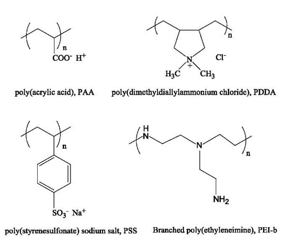
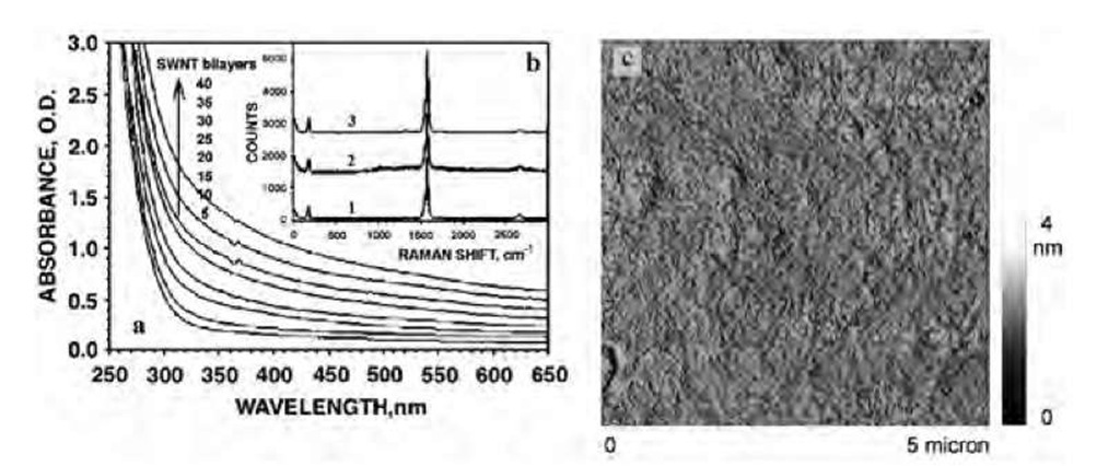
The presence of carboxylic acid groups affords the preparation of metastable SWNT dispersions after 1-min sonication in deionized water without any additional surfactant. Thus-prepared, negatively charged SWNT with a zeta potential of — 0.08 V can be layer-by-layer assembled with positively charged polyelectrolyte, such as branched poly(ethyleneimine) (PEI; Mw = 70,000) (Fig. 1). Because the overall negative charge of the SWNT used here was fairly small, a layer of SWNT was replaced with a layer of poly(acrylic acid) (PAA; Mw=450,000) after every fifth deposition cycle (Fig. 1). These additional layers improve the linearity of the deposition process and present a convenient chemical anchor for subsequent chemical modification. For the same reasons, a single PEI/PAA bilayer was deposited on a bare glass or Si substrate before the SWNT assembly. The assembly conditions of the entire procedure (pH, ionic strength, concentrations, etc.) were optimized so that the dipping cycles can be repeated as many times as needed with linear growth of the multilayers (Fig. 2a). This enables the preparation of films with any desirable thickness and architecture tailored to different applications. The ionic conditions of LBL assembly were the following: 1% solution of PEI at pH 8.5; 1% PAA at pH 6 (pH 3 for wafer coating); SWNT at pH 6.8. All solutions were made in 18 MO deionized (DI) water without addition of any extra salt or other low molecular weight electrolyte. Deionized water was also used for rinsing at pH 8.5, adjusted by NaOH. Wafers and glass slides were cleaned in piranha solution, rinsed with DI water, sonicated for 15 min, and again thoroughly rinsed with DI water. After that, they were coated with a precursor layer: PEI (10 min) + PAA(15 min, pH 3), followed by the deposition of (PEI/SWNT)5. The layer sequence of (PEI/ PAA)(PEI/SWNT)5 was repeated until the desirable thickness was obtained. Exposure times of 10 and 60 min was used for polylectrolytes and SWNT baths, respectively.[18,19]
Fig. 1 Common polyelectrolytes used for LBL process.
Fig. 2 Structural characterization of SWNT multilayers. (a) Sequential UV-vis spectra of a glass substrate in the course of the LBL deposition of SWNT. The spectra were taken for a total number of (PEI/SWNT) bilayers indicated in the graph. (b) Raman scattering spectra of SWNT dispersion (1), LBL film on a glass substrate (2), and freestanding film (3). (c) Tapping mode AFM image (DI, Multimode IIIA) of a Si wafer bearing (PEI/PAA)(PEI/SWNT)5.
Multilayer stacks with a cumulative structure of [(PEI/ PAA)(PEI/SWNT)5]6 and [(PEI/PAA)(PEI/SWNT)5]8 containing 30 and 40 (PEI/SWNT) bilayers, respectively, were typically used in this study.
We are currently investigating other methods of SWNT dispersion in water to avoid excessive damage to the SWNT wall, for example, wrapping the nanotubes with copolymers, which can work equally well on the SWNT and multiwalled carbon nanotubes (MWNT). For some applications, MWNTs can be the preferred materials because of their lower cost.
Similarly to other polyelectrolyte LBL systems,[15] a submonolayer of SWNT is deposited in each deposition cycle. The final morphology of the multilayers can be described as a mixture of individual carbon nanotubes and their 4-9-nm bundles intricately interwoven together in a fine fabric (Fig. 2c). Two important structural characteristics should be pointed out. Single-walled carbon nano-tubes uniformly cover the entire surface of the substrate without any evidence of phase separation. Also, the presence of oxidized flat graphite sheets and other forms of carbon colloids in our experiments was very small. Both these factors contributed to the mechanical properties of the composites. The quality of the nanotube material was also assessed by Raman spectroscopy. (Raman measurements were performed in a backscattering configuration with 50 mW of 514.5-nm laser light incident on the samples). The characteristic Raman peaks for SWNTs, e.g., the radial breathing mode at —182 cm"1 and the tangential C-C stretching modes located at —1560 cm"1 (G1 mode) and — 1583 cm"1 (G2 mode), were very sharp and narrow, indicating the high uniformity of the SWNT and low level of impurities present in the films. A barely visible peak at —1340 cm"1 (D mode) revealed the presence of residual amounts of disordered carbon structures. Using the correlation between the frequency of the radial breathing mode, v, and the SWNT diameter, d, expressed as d=223.75/v,[23] a value of d =1.2 nm is obtained, which is in a good agreement with the SWNT diameters obtained from atomic force microscopy (AFM) images of many individual nanotubes. From these images, the length of the nanotubes was estimated to be 2-7 mm.
Poly(ethyleneimine) was utilized as the LBL partner of SWNT because of the terminal -NH2 and backbone -NH-groups in the main chain and branches suitable for the subsequent chemical modification of the composite.[24] The PEI chains can be cross-linked 1) with each other and 2) with carboxyl groups on SWNT and PAA. Chemical stitching increases the connectivity of the polyelectrolyte matrix with SWNT, and therefore, the load transfer in the composite.1-13-1 We used here the combination of both modification pathways. Partial covalent SWNT-PEI-PAA cross-linking was achieved by heating the films to 130°C after the deposition of each layer, resulting in amide bonds between a variety of protonated and nonprotonated functional groups of PEI, PAA, and SWNT complementing the intrinsic ionic cross-linking of the LBL films.[25] Subsequently, the film was exposed to glutaraldehyde at room temperature. The sample was cross-linked in 0.5% glutardialdehyde solution in phosphonate buffer (0.054M Na2HPO4, 0.013 M NaH2PO4, pH 7.4) for 1 hr at room temperature. To remove unreacted glutardialdehyde, the film was rinsed with tap water for 3 x 10 min and then with DI water the same number of times. This reaction produces a tight network of polymeric chains and nanotubes connected by dialdehyde linkages. It was found that if only 1% of all carbon atoms of SWNT are chemically bonded to the polymer matrix, such cross-linking drastically increases the sheer between them by an order of magnitude.[13] Therefore a 5% density of -COOH groups on the SWNT surface cited above should be sufficient to obtain good connectivity with the polyelectrolyte matrix. Note that these groups are not completely utilized at the moment because of the relatively low temperature of the amide bond cross-linking step.
Fig. 3 Electron microscopy of the rupture region in SWNT multilayers. (a) Scanning electron microscopic image of the surface and broken edges of [(PEI/PAA)(PEI/SWNT)5]8. (b, c) Transmission electron microscopic images of ruptured areas of the freestanding films. The arrows indicate the likely stubs of the broken nanotube bundles. They were identified as such because 1) their diameters are both equal to that of the actual SWNT bundle bridging the gap and 2) their mutual positioning presents a virtually perfect match with the expected location of the ends of a bundle broken during gap opening.
The mechanical properties of the LBL-assembled SWNT thin films were studied in their freestanding form prepared by the chemical delamination from the sub-strate.[21] Multilayers of SWNT were separated from the silicon wafers by immersion into 0.5% aqueous HF for 3 min The Raman scattering spectrum of the separated film is almost identical to that of the supported film and original nanotubes (Fig. 2b), demonstrating that the structure of SWNT remains mostly unaltered during cross-linking and delamination. The breathing mode frequency shifts from 185 cm— 1 in the assembled film to 182 cm— 1 in the cross-linked, self-standing films, indicating a small expansion of the tube diameters.[18,19]
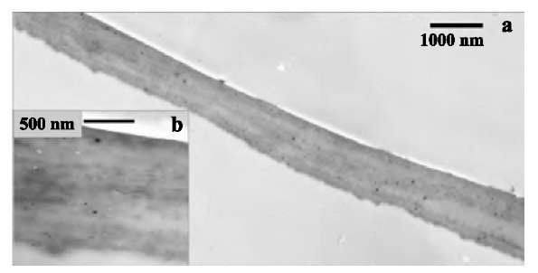
The delaminated thin films (Fig. 3a) can be easily handled in a variety of ways. They can be made of any desirable size or shape determined only by the dimensions of the substrate. The films that we routinely prepare in this study were ca. 1 x 3 cm. Assemblies with a structure of [(PEI/PAA)(PEI/SWNT)5]6 and [(PEI/PAA)(PEI/ SWNT)5]8 displayed an SWNT content of 50±5 wt.% as calculated from carbon and nitrogen energy-dispersive X-ray analysis (EDAX) peak integrals. Previously reported composites made with modified SWNT revealed strong inhomogeneities even at SWNT loadings as low as 6-8%.[8,9] The cross-sectional image of the freestanding film (Fig. 4a,b) clearly demonstrates the absence of micron-scale inhomogeneities although the occasional inclusion of round 30-60 nm particles can be seen (possibly dust). The slight variations in the gray-scale contrast between different strata show the actual variations in SWNT distribution within the sample. They originate from small deviations in SWNT adsorption conditions, such as dispersion concentration and pH, during the buildup procedure. In scanning electron microscopy (SEM) (Fig. 3a), the surface of the sample also appears smooth and continuous. Typically, the separation of single-walled or multiwalled carbon nanotubes and their bundles in mixed polymer composites can be observed as whiskers clearly visible in transmission electron microscopy (TEM) and SEM images.[4,26] The TEM examination of the initial stages of rupturing showed that virtually no fiber pullout occurs in the LBL multilayers (Fig. 3b). This can be contrasted by extensive nanotube pullout reported before by several groups.[4,26] For many TEM images obtained in different areas of the self-standing films, we were able to observe only one SWNT bundle bridging the break region (Fig. 3c). The same image also shows two broken carbon fiber stubs embedded in the walls of the crack (marked by arrows in Fig. 3c). In total, the microscopy results indicate the efficient load transfer in the LBL composite. Similar films are currently prepared from the multiwalled carbon nanotubes utilizing the polymer wrapping (Fig. 5).
Fig. 4 Transmission electron microscopic examination of the homogeneity of the SWNT LBL film. Survey (a) and close-up (b) TEM images of SWNT film cross sections. The top and bottom sides of the film are slightly different in roughness: The one that was adjacent to the flat substrate is smoother than the ”growth” surface of the film.
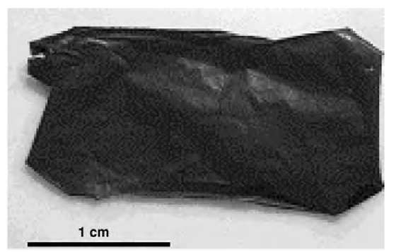
Fig. 5 Optical photograph of the free-standing LBL films made from multiwalled carbon nanotubes.
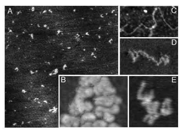
The mechanical properties of the layered composites were tested on a custom-made thin-film, tensile-strength tester (McAllister Inc.) recording the displacement and applied force by using pieces cut from [(PEI/PAA)(PEI/ SWNT)5]6 and [(PEI/PAA)(PEI/SWNT)5]8 freestanding films. The tester was calibrated on similar pieces made from cellulose acetate membranes and Nylon threads. [(PEI/PAA)(PEI/SWNT)5]6 and [(PEI/PAA)(PEI/ SWNT)5]8 samples had an average TEM thickness of 0.75 and 1.0 mm, respectively. Their typical stress (s) vs. strain (e) curves differed quite markedly from stretching curves previously seen for SWNT composites[10] and for LBL films solely made from polyelectrolytes, (PEI/ PAA)40, obtained by the same assembly procedure (Fig. 6b). They displayed a characteristic wave-like pattern, gradual increase of ds/de derivative, and the complete absence of the plateau region for high strains corresponding to plastic deformations (Fig. 6a). The latter correlates well with the enhanced connectivity of SWNT with the polymer matrix (Fig. 3). Other mentioned stretching features indicate the reorganization of the layered composite under stress. A process similar to the sequential breakage of cross-linked parts of coiled molecules (see AFM image in Fig. 2) observed in natural nanocomposites, such as seashells and bones,[27,28] is likely to be responsible for the wave-like pattern and the increase of the stretching curve slope. This statement can be substantiated by the AFM investigation of the single molecules of a polyelectrolyte adsorbed to the substrate (Fig. 7). Atomic force microscopy images of poly-(diallydimethylammonium) chloride (PDDA) (Fig. 7) polycation adsorbed to silicates revealed the actual conformation of macromolecules at the organic-inorganic interface. Similarly to PEI, this polyelectrolyte has a positive charge when adsorbed to silica or glass. Coiling of PEI is expected to be even stronger than that of PDDA because the latter has intrinsically strong propensity to form a rod-like structure because of its greater charge. The intentionally rarified submonolayers of polycation were made from 2x 10" 7 wt.% solutions to resolve single chains (Fig. 7A). These are intricately entangled to form a continuous film at higher concentrations. Adsorbed polyelectrolyte were found to be present in the film in different conformational states: extended (Fig. 7C), partially coiled (Fig. 7D), and tightly coiled (Fig. 7E). The length of the macromolecules in extended conformation, 350-400 nm (Fig. 7C), coincides with that expected for poly(diallydimethylammonium) chloride with Mw= 200,000. As can be seen from Fig. 7A, most of the molecules (>75%) are present in the tightly coiled conformation. Moreover, the AFM examination of the clusters of the macromolecules molecules (Fig. 7B) demonstrates that this is apparently the preferential conformation of the polyelectrolyte in densely packed films made at higher concentrations used for multilayer preparation.1-29-1
Fig. 6 Typical tensile-strength curves of the SWNT LBL films. Stress-strain dependence for (a) [(PEI/PAA)(PEI/SWNT)5]8 and (b) a similar free-standing multilayer film solely made from polyelectrolytes. The dependence of the mechanical properties of the cross-linked LBL composites on humidity was tested in the range of relative humidity of 30-100%, T =298°C, and was found to be negligible.
Fig. 7 Atomic force microscopy of rarified PDDA films. (A) Overview of adsorbed PDDA molecules (2 x 2 mm, mica). (B) Cluster of PDDA molecules (360 x 230 nm, Si wafer). (C) Fully extended PDDA chain (350 x 170 nm). (D) Partially coiled PDDA chain (160 x 80 nm, mica). (E) Typical highly coiled conformation of PDDA chain (100 x 110 nm).
Considering the complexity of the deformation process, the assessment of elastic and inelastic behavior in each part of the curve will be carried out upon detailed microscopic investigation. Meanwhile, the values of ds/de exceeding 50 GPa should be noted.
The comparison with stretching curves of polyelectro-lytes (Fig. 6b) shows that the incorporation of nanotubes in the LBL structure resulted in the transfer of the SWNT strength to the entire assembly. The stretching curves of the SWNT multilayers display a clear break point. The ultimate tensile strength, T, was found to be 220 ±40 MPa with some readings being as high as 325 MPa. This is several times to an order of magnitude greater than the tensile strength of strong industrial plastics with T =20-66 MPa.[30] It is also substantially higher than the tensile strength of carbon fiber composites made by mixing: Polypropylene filled with 50 vol.% carbon fibers has T= 53 MPa.[31] A recent study on SWNT-poly(vinylalcohol) ribbons with axially aligned nanotubes reported a tensile strength of 150 MPa.[10] The T values obtained for SWNT LBL films are in fact close to those of ultrahard ceramics and cermets such as tungsten monocarbide (T =340 MPa), silicon monocarbide (T =300 MPa), and tantalum mono-carbide (T = 290 MPa).[30] Such strength and failure strain greater than in cermets (ca. >1% in SWNT LBL vs. 0.20.6% in carbides) displayed by an organic composite is quite remarkable.
The tensile strength of single carbon nanotubes was experimentally determined to be between 13 and 50 GPa.[26,32] The lower values obtained for the SWNT multilayers should be mainly attributed to the contribution of polyelectrolytes and some uncertainty in the actual cross-section area at the break point and a degree of cross-linking. The mixing law predicts that polyelectro-lyte matrix with T=9 MPa makes negligible contribution to the strength of the composite while taking about 50% of its volume fraction. [SWNT is d = 1.14 g/cm3. Because the density of the polyelectrolytes used for the preparation of the multilayers (i.e., PDDA d =1.04 g/cm3; PAA d =1.14 g/cm3) is almost the same, the volume fraction of SWNT in the composite can be considered to be equal to the mass fraction.] Additionally, the decrease of the mechanical strength of the nanotubes in the process of ionic functionalization (estimate 15%)[33] should also be considered as a factor affecting the strength of these composites. These issues are pointed out as means of further optimization of the multilayers. Tuning of their molecular structure and composition should lead to vast improvement of their mechanical properties that could possibly approach those of pristine carbon nanotubes.
It is also interesting to compare the T values for SWNT composite films to those obtained for other LBL films made with other inorganic components such as montmo-rillonite platelets, M, and nanoparticles, NP, for instance 8-10-nm magnetite nanoparticles. The freestanding films (PDDA/NP)40 and (PDDA/NP/PDDA/M)40 made according to Ref. [21] revealed T equal to 40 and 72 MPa, respectively. In conjunction with the tensile strength data (see above), it can be concluded that inorganic or SWNT components act as a molecular armor in the layered composites significantly reinforcing them. The molecular organization of the material made possible the transfer of a part of their strength to the entire assembly.
CONCLUSION
The technology of the preparation of nanocomposites described above should be considered as an effective tool in developing new ultrastrong materials. High structural homogeneity and interconnectivity of the structural components of the LBL films combined with high SWNT loading leads to significant increase of the strength of nanocomposites, being somewhat weaker than some other organic and carbon fiber materials but at the same time being far beyond their potential as ultrastrong composites. The described technique minimizes the structural defects originating from phase segregation and opens a possibility for the molecular design of layered hybrid structural materials from different polymers and other nanoscale building blocks. The prepared freestanding membranes can serve as a unique component for a variety of technologies. One of its great advantages over other technologies is the ability to prepare ultrathin ultrastrong membranes with minimal heterogeneity. We expect these composite materials to be used initially in high-value applications, most possibly as a critical part of a space or biomedical device. Once the carbon nanotubes become less expensive and the LBL processing becomes a routine operation, the same composites can be utilized in more high-volume products such as building construction materials and car components. At the same time, the less-expensive alternatives to the ultrastrong composites with comparable performance can be developed from carbon- or ceramics-based nanomaterials.
![Electron microscopy of the rupture region in SWNT multilayers. (a) Scanning electron microscopic image of the surface and broken edges of [(PEI/PAA)(PEI/SWNT)5]8. (b, c) Transmission electron microscopic images of ruptured areas of the freestanding films. The arrows indicate the likely stubs of the broken nanotube bundles. They were identified as such because 1) their diameters are both equal to that of the actual SWNT bundle bridging the gap and 2) their mutual positioning presents a virtually perfect match with the expected location of the ends of a bundle broken during gap opening. Electron microscopy of the rupture region in SWNT multilayers. (a) Scanning electron microscopic image of the surface and broken edges of [(PEI/PAA)(PEI/SWNT)5]8. (b, c) Transmission electron microscopic images of ruptured areas of the freestanding films. The arrows indicate the likely stubs of the broken nanotube bundles. They were identified as such because 1) their diameters are both equal to that of the actual SWNT bundle bridging the gap and 2) their mutual positioning presents a virtually perfect match with the expected location of the ends of a bundle broken during gap opening.](http://what-when-how.com/wp-content/uploads/2011/03/tmp25F117_thumb1_thumb.jpg)
![Typical tensile-strength curves of the SWNT LBL films. Stress-strain dependence for (a) [(PEI/PAA)(PEI/SWNT)5]8 and (b) a similar free-standing multilayer film solely made from polyelectrolytes. The dependence of the mechanical properties of the cross-linked LBL composites on humidity was tested in the range of relative humidity of 30-100%, T =298°C, and was found to be negligible. Typical tensile-strength curves of the SWNT LBL films. Stress-strain dependence for (a) [(PEI/PAA)(PEI/SWNT)5]8 and (b) a similar free-standing multilayer film solely made from polyelectrolytes. The dependence of the mechanical properties of the cross-linked LBL composites on humidity was tested in the range of relative humidity of 30-100%, T =298°C, and was found to be negligible.](http://what-when-how.com/wp-content/uploads/2011/03/tmp25F120_thumb_thumb.jpg)
