FERROHYDRODYNAMICS
Ferrohydrodynamic Bernoulli’s Law
The magnetic force density acting on an incompressible ferrofluid is:
so that ferrofluids move in the direction of increasing magnetic field strength.
When MM and H are collinear, this force density modifies Bernoulli’s equation for inviscid and irrotational flow to:
where p is the ferrofluid mass density [in kg/m3], C is the velocity potential defined as v = — VC, p is the pressure [in Pa], v|v| is the magnitude of the fluid velocity v =, g is the gravitational acceleration vector, and r=xix+yiy+ziz is the position vector. The magnetic term in Eq. 11 is the magnetic contribution to fluid pressure and describes such magnetic effects as the shape of a ferrofluid meniscus; flow and instabilities of a ferrofluid jet such as for magnetic fluid inkjet printing; operation of magnetic fluid seals, bearings, and load supports; magnetic fluid nozzles; and magnet self-levitation in a ferro-fluid.[1,74] Ferrofluids in a nonuniform magnetic field can be used to separate material mixtures according to their densities, known as sink-float separation. With gravity directed in the — z direction, the apparent density of ferrofluid with density p when H = 0 is:[35]
Fluid Instabilities
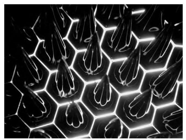
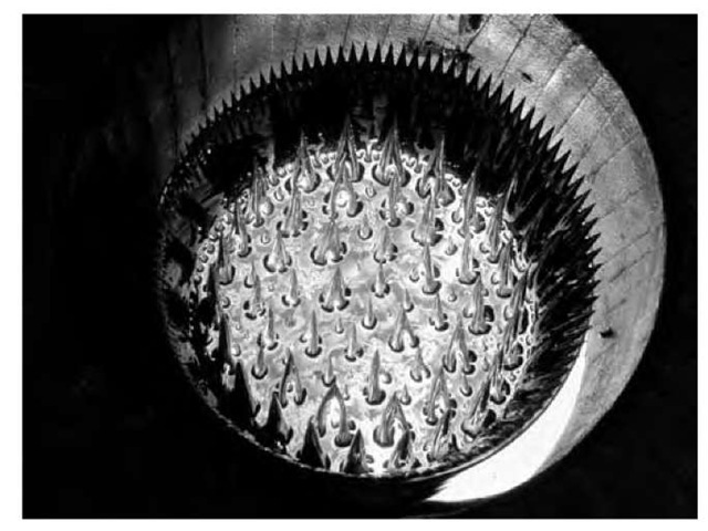
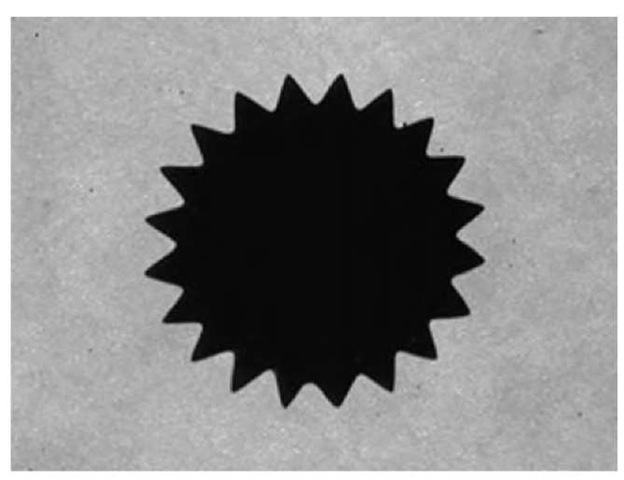
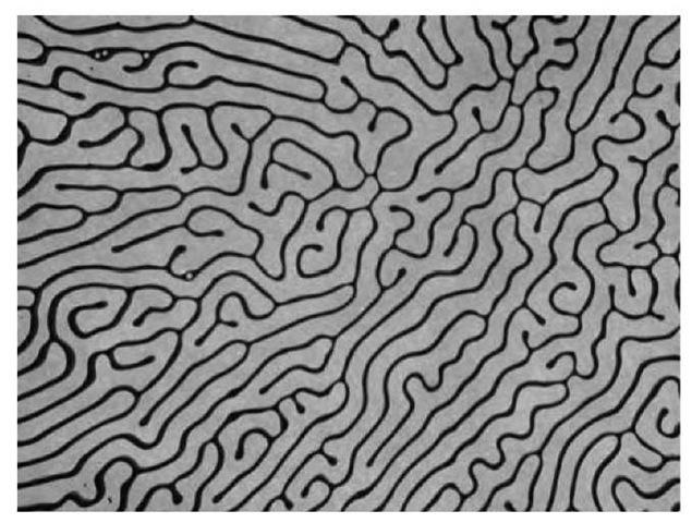
Ferrofluids exhibit a wide range of very interesting lines, patterns, and structures that can develop from ferrohy-drodynamic instabilities.[61] Figs. 4 and 5 illustrate the ferrofluid hexagonal peaking behavior resulting from a magnetic field perpendicular to the free surface of a ferrofluid layer.[1,75,76] The peaks initiate when the magnetic surface force exceeds the stabilizing effects of fluid weight and surface tension. In Fig. 6, the gearlike structure results from the radial perpendicular field instability when a small magnet is placed behind a ferrofluid drop confined between closely spaced glass plates. In a rotating magnetic field, this ”star wheel” will rotate and can function as a gear, flow stirrer, or pump. Possible further microdevice and nanodevice applications could result from solid structures made from a ferrofluid that is solid at room temperature but becomes liquid at slightly elevated temperature, such as by using a paraffin-based ferrofluid. If the ferrofluid is heated and then cooled in the presence of a magnetic field, solid magnetic nanostructures can be fabricated such as the gearlike structure in Fig. 6. Solid spiked structures with shapes like those in Figs. 4 and 5 may be useful for forming high electric fields at the tips that can be used in charge injection devices. Fig. 7 shows the labyrinth instability that results when a magnetic field is applied tangent to the thin dimension of the ferrofluid layer confined between closely spaced glass plates.[77-79] The labyrinth forms because the induced magnetic poles on the top and bottom surfaces of the ferrofluid create a magnetic field that opposes the applied field, the so-called demagnetization field, so that the magnetic field in the ferrofluid is less than the magnetic field in the nonmagnetic region outside the ferrofluid. Because the ferrofluid is attracted to regions of strong magnetic field, a comblike interfacial instability develops and the interface forms thin lines that move away from the ferrofluid layer. Such fine lines may be useful for lithography and printing applications.
Fig. 4 Hexagonal peaking patterns of about 1 cm spacing result when a perpendicular magnetic field is applied to a layer of Isopar M magnetic fluid with saturation magnetization of 400 G. The peaks initiate when the magnetic surface force exceeds the stabilizing effects of the fluid weight and surface tension. The image with a magnetic field of about 330 G shows the sharp peaks with a hexagonal base pattern.
Fig. 5 Another view of the perpendicular field instability including a crown of peaks on the glass container wall edge when a 400-G magnetic field is applied to Isopar M ferrofluid. The containing vessel has a 15 cm diameter.
Fig. 6 Gearlike structure that results when a small 5-mm-diameter permanent magnet, with strength of about 1200 G, is placed behind a small Isopar M ferrofluid droplet confined between glass plates with 1 mm gap.
Fig. 7 Labyrinth instability that results when a 1-mm-thick layer of Isopar M ferrofluid between glass plates is stressed by a magnetic field of about 150 G tangent to the thin dimension of the ferrofluid layer. The line thickness is about 200 mm.
Rotating Magnetic Field Torque-Driven Phenomena
Attention has shifted to rotating magnetic field phenomena, where the magnetization relaxation time constant of Eq. 5 creates a phase difference between magnetization and magnetic field, so that M and H are not in the same direction. This causes a magnetic torque density:[55-63]
which causes the magnetic nanoparticles and surrounding fluid to spin. The concerted action on the order of 10221023 nanoparticles/m3 leads to interesting microdrop behavior. A ferrofluid spherical microdrop, about 20 mm in diameter, in a rotating magnetic field of intensity from 50 to 1000 A/m over a frequency range of 4 Hz-4 kHz forms a set of complicated shapes of loops, worms, and stars at intermediate strength fields and a ”spinning starfish” shape with many arms at high magnetic field, all corotating with the magnetic field.[53]
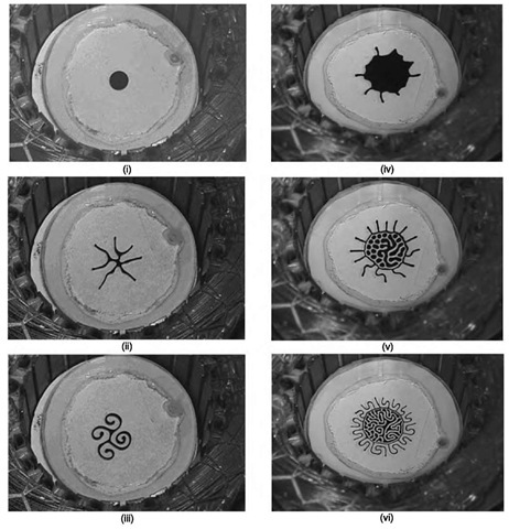
Other new ferrohydrodynamic phenomena with simultaneously applied d.c. and rotating magnetic fields are shown in Fig. 8 for a ferrofluid contained between glass plates with a 1.1 mm gap.[80,81] Two experiments are shown in Fig. 8. The first experiment, images (i)-(iii), uses 50 mL of ferrofluid, brings the d.c. axial field up to 100 G, and then turns on the clockwise rotating field. Image (i) shows the circular ferrofluid drop before the magnetic field is applied, whereas image (ii) shows the spiking labyrinth pattern formed by the ferrofluid after only the d.c. axial field has been applied. Then the clockwise rotating field is applied and the spikes begin to curl in on themselves, eventually forming the smooth spiral pattern shown in image (iii) after some of the spikes are absorbed into the larger structure. The smooth spirals form as the clockwise rotating magnetic field causes counterclockwise viscous shear flow on the outside ferrofluid surfaces, which returns on the inside surfaces.
Fig. 8 Spiral and intricate structure shapes with simultaneously applied d.c. and 20-G, 25-Hz rotating magnetic fields to fluorocarbon-based ferrofluid drops with ~ 400 G saturation and low field magnetic susceptibility ~ 3 confined between two glass plates with a 1.1 mm gap. The ferrofluid is surrounded by a 50/50 mixture of isopropyl alcohol and deionized water, which prevents ferrofluid wetting of the glass plates. (i)-(iii) have 50 mL of ferrofluid. (i) shows the ferrofluid drop before the magnetic field is applied. (ii) The d.c. axial field is first increased to 100 G to cause the radially spiking labyrinth pattern. (iii) The clockwise rotating field is turned on and the spikes begin to curl in on themselves, forming a smooth spiral pattern. (iv)-(vi) have 200 mL of ferrofluid. The test cell is first placed in the clockwise rotating field, which causes a counterclockwise flow that holds the fluid drop together without spikes. In (iv), a 100-G d.c. axial field is then gradually applied, causing the ferrofluid drop to appear to expand before the phaselike transition to (v) at a critical d.c. magnetic field strength around 100 G. (vi) The magnetic field is increased from 100 to 250 G.
The second experiment, with 200 mL of ferrofluid, is seen in images (iv)-(vi) and is the result of first placing the cell in the clockwise rotating field and then gradually applying a 100-G d.c. axial field. This results in the originally round ferrofluid drop appearing to expand in image (iv) before the phase transition to image (v) at a critical d.c. magnetic field strength around 100 G, evolving to image (vi) as the d.c. magnetic field is further increased to 250 G.
These intricate patterns can possibly have applications as self-assembling structures in fluidic devices, printing, separations, etc.
Application to Power Transformer Cooling
With the development of a ferrofluid transformer oil that meets electrical property and breakdown requirements of high-power transformers,[82] there has been recent applied research[83-92] to use ferrofluid physical, mechanical, and thermal properties together with the magnetic body force density of Eq. 10 for enhanced cooling of power transformers. Heat generated by the windings and magnetic core produces temperature gradients in the ferro-fluid, where there is also a nonuniform magnetic field. It is also thought that the high a.c. magnetic field in the vicinity of the windings and oil ducts can cause magnetic particle stirring that reduces ferrofluid thermal gradients. Measurements for 10- and 50-kVA transformers showed up to about 12°C lower operating temperature for ferrofluid transformer oil than for nonmagnetic transformer oil.[88,89] Because the 10 -nm-diameter ferrofluid particles are so small, they appear to have no deleterious effect on the oil electrical breakdown strength.[90] The enhanced cooling method uses the temperature dependence of ferrofluid magnetization described by the Langevin relation, so that the magnetic susceptibility wm in Eq. 7 decreases as temperature increases. Thus, hot ferrofluid in the vicinity of the transformer windings has a lower magnetic permeability than cold ferrofluid. Then, cool (high magnetic permeability) ferrofluid is attracted to high magnetic field regions near the transformer windings as hot (low magnetic permeability) ferrofluid is displaced. Thus, the temperature gradients in a transformer can be used to induce magnetic permeability gradients that cause cooling ferrofluid motion and the resulting convective flow enhances transformer cooling. As an additive, a ferrofluid concentrate can be used to extend the lives of millions of aging transformers. As a new technology, ferrofluid transformers may be smaller, more efficient, and possess improved dielectric capabilities. A related analysis models a laminar and turbulent pipe flow that is applicable to transformer duct flows and validates a set of ferrohydrodynamic equations including the effects of nanoparticles interacting with magnetic fields and thermal/flow gradients.[93]
APPLICATIONS TO NANOELECTROMECHANICAL AND MICROELECTROMECHANICAL SYSTEMS
Advantages of Magnetic Field Devices
To demonstrate the advantages of magnetic field-based microelectromechanical systems (MEMS) and nanoelec-tromechanical systems (NEMS) devices over the usual electric-field based devices, we can compare representative electric and magnetic energy densities.[61] An electric field device is generally limited by the maximum allowed electric field without electrical breakdown, typically E « 108 V/m for small-scale devices that take advantage of the Paschen curve at small gaps to raise the electrical breakdown strength of air (e.g., a variable capacitance micromotor may use 150 V across a 1.5-p.m gap).[94] Magnetic field devices have no limitations analogous to electrical breakdown and the maximum magnetic flux density is on the order of the saturation magnetization of single-domain magnetic nanoparticles, which is about B « 2.1 T for single-domain iron particles. The resulting electric and magnetic energy densities are then:
This possible increase in energy density and corresponding forces for magnetic devices has the added advantage of increased reliability as there are no catastrophic failure mechanisms analogous to electrical breakdown. Potential new NEMS applications using ferrofluid nanoparticles, with and without carrier fluid, include nanoduct flows, nanomotors, nanogenerators, nanopumps, nanoactuators,and other similar nanoscale devices.[61,95]


