As stated earlier, the commonly used methods of speed control are open and closed loop. If speed regulation is not a factor, then a DC motor can be operated in open-loop control. However, most applications require some type of regulation to gain the most efficient use of the mechanics of the system. Therefore, a means of sending the drive an actual speed signal is essential to speed regulation. In DC drives there are basically two forms of closed-loop control—tach feedback and armature voltage feedback (EMF control). Though armature voltage feedback does not use an external device, it is termed feedback and can be considered a form of closed-loop control.
Armature Voltage Feedback (EMF Control, Speed Regulation)
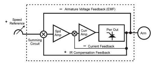
Figure 5-13 shows an armature voltage feedback control scheme.

Figure 5-13. Armature voltage feedback (EMF control)
As shown in Figure 5-13, the drive requires a speed reference signal and a feedback signal of opposite polarity. The feedback is used to balance the control when the desired output speed is reached. All of the drive control systems are within the dotted lines.
A speed reference is sent to the summing circuit. By sensing the armature voltage at the drive output, the drive can sense the CEMF (Counter Electromotive Force) of the motor. This CEMF signal (negative polarity) is sent
as feedback to the summing circuit. When the error is at zero, the drive will stabilize at the desired speed.
Another summing circuit is located after the speed amplifier and before the current amplifier. This summing circuit would use a shunt or other device to sense the armature current. The negative current feedback is sent to the summing circuit, with the resulting signal used to limit the amount of current output. If the current level is within limits, then the speed signal will be in control. But if the current exceeds the limits, it will lower the speed control until the current is reduced to a safe level.
With armature voltage feedback, motor speed tends to droop between full-load and no-load situations. To help compensate for this speed “droop,” a feedback called IR compensation (an acronym for “current resistance” compensation due to a voltage drop across the armature due to load -E=IXR, Ohm’s Law) is included in the drive. This circuit senses the armature current and feeds a small additional signal back to the speed amplifier.
At the summing circuit, three signals exist: positive speed reference, negative armature voltage feedback (EMF), and positive IR compensation. The IR compensation signal adds to the speed reference signal to compensate for speed droop created by the load.
With three signals summing at the same point, there is a possibility for instability. To set up IR compensation properly, speed and armature voltage feedback adjustments should be made with the IR compensation off. While observing the motor during speed step changes, IR compensation is gradually increased until oscillation occurs. Then IR compensation is decreased until the oscillation (instability) stops. Speed regulation of 2-3% is possible with this type of feedback control.
Armature Voltage Feedback (EMF Control, Torque Regulation)
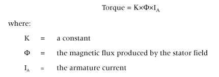
The relationship between torque regulation and speed regulation in a standard DC drive configuration illustrates the importance of torque response. Since the armature current in a DC motor directly determines torque, the DC controller is configured as a closed-loop current regulator, using armature voltage feedback (EMF). The speed regulator then commands the current regulator to produce whatever torque is required to maintain the desired speed.
Torque-regulating drives are often used in load-sharing applications where a speed-regulating drive controls the speed of the driven machine, while a torque-regulated “helper” drive provides a controlled level of torque at some other location on the machine. If the load does not restrict the speed of a torque-regulated drive, the drive speed could exceed the safe operating limit. Therefore torque-regulating drives must have a speed-limiting mechanism that prevents the speed from exceeding a safe limit if the torque presented by the driven machine drops to zero.
With a DC drive, torque can be regulated directly by regulating armature current. In any motor, torque is the result of the force between two magnetic fields. In a motor (DC), torque is easily and directly regulated by regulating the currents that control the flux in the two magnetic fields. The field winding flux is the motor’s magnetizing flux, which is held constant by providing a constant field current. The motor’s torque-producing flux is the flux created by the armature current, which is controlled to regulate torque. The torque produced at any speed is given by:

Tachometer Feedback
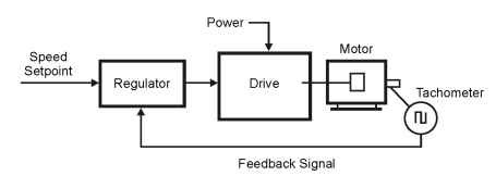
When DC motor speed is of primary concern, it can be measured with a transducer and regulated with a closed-loop regulator as shown if Figure 5-14.

Figure 5-14. Closed-loop speed regulation—tach feedback
The transducer in Figure 5-14 is a tachometer generator. As previously reviewed, a tach is a small generator that produces an output voltage that is very accurately determined by its operating speed. There are also pulse tachs, which provide a train of voltage pulses at an average frequency that is exactly proportional to average speed.
The closed-loop speed regulator compensates for any changes in the characteristics of the drive caused by changes in load or by outside influences such as line voltage and ambient temperature. With a closed-loop speed regulator, the most important characteristic of the drive is its ability to rapidly respond to changes in requirements for torque.
The transducer devices already presented would be involved in generating the actual speed feedback signal. The accuracy of the system will be dic-
tated by the regulation of the feedback device and the responsiveness of the drive control.
