1.4
The 6812 is currently available in two implementations, which are designated the MC68HC812A4 (abbreviated the ‘A4) and MC68HC912B32 (abbreviated the ‘B32). These are discussed herein.
The ‘A4 can operate in the single-chip mode or the expanded bus mode. In the single-chip mode, the *A4 can be the only chip in a system, for it is self-sufficient. The processor, memory, controller, and I/O are all in the chip. (See Figure 1.11.) The memory consists of IK words of RAM and 4K words of electrically erasable programmable memory (EEPROM). The I/O devices include a dozen parallel I/O registers, a serial peripheral interface (SPf), a serial communication interface (SCf), a timer, and an AID converter.
The ‘ A4′s expanded bus mode removes three or four of the parallel ports, using their pins to send the address and data buses to other chips. RAM, ROM, erasable programmable read-only memory (EPROM), and programmable read-only memory (PROM) can be added to an expanded bus. In a narrow expanded mode, ports A and B are removed for address lines, and port C is an 8-bit data bus. Port D is available for parallel I/O. In a wide expanded mode (see Figure 1.12), ports A and B are removed, their pins are used for the address bus, and ports C and D are a 16-bit data bus. Port D is unavailable for parallel I/O. In both modes, ports E, F, and G are available for bus control, chip selects, and memory control, or else for parallel I/O.
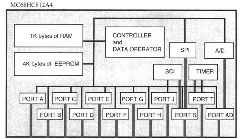
Figure 1.11. Single-Chip Mode of the MC68HC812A4
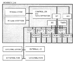
Figure 1.12. Expanded Wide Multiplexed Bus Mode of the MC68HC812A4
A memory map is a description of the memory showing what range of addresses is used to access each part of memory or each I/O device. Figure 1.13a presents a memory
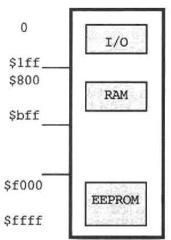
a. for the MC68HC812A4
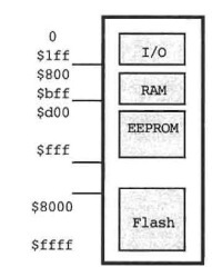
b.for the MC68HC912B32
Figure 1.13. Memory Maps for the 6812
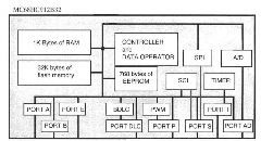
Figure 1.14. Single-Chip Mode of the MC68HC912B32
map for the ‘A4. Actually, EEPROM, RAM, and I/O may be put anywhere in memory (on a 2K or 4K boundary), but we will use them in the locations shown in Figure U3a throughout this text. I/O is at lowest address, and RAM is at $800 to $bff. The EEPROM at $F000 has a monitor. Usually your data is put in RAM, and your program may be put in RAM or in EEPROM.
The ‘B32 can also operate in the single-chip mode or the expanded bus mode, but in the latter mode, address and data are time-multiplexed on the same pins. In the single-chip mode, the ‘B32 can be the only chip in a system. The processor, memory, controller, and I/O are all in the chip. (See Figure 1.14.) The controller and data operator execute the 6812 instruction set discussed earlier. The memory consists of IK words of RAM, 768 bytes of EEPROM, and 32K words of flash memory, which is like EEPROM. The I/O devices include eight parallel I/O registers, a serial peripheral interface (SPI), a serial communication interface (SCI), a timer, a pulse-width modulator (PWM), a Byte Data Link Communication Module (BDLC), and an A/D converter.
The expanded bus mode of the ‘B32 removes two of the parallel ports, ports A and B, using their pins to send the time-multiplexed address and data buses to other chips. The address and data buses are time-multiplexed; in the first part of each memory cycle, the 16-bit address is output on the pins, and in the second part, data is output or input on the indicated pins. In a narrow expanded mode, port A is used for an eight-bit data bus. In a wide expanded mode (see Figure 1.15), ports A and B pins are used for a 16-bit data bus. In both modes, port E can be used for bus control or else for parallel I/O. RAM, ROM, EPROM, and PROM can be added to the expanded bus.
Figure 1.13b presents a memory map for the ‘B32. I/O is at lowest address, and RAM is at $800 to $bff. A small EEPROM is at $d00 to $fff. Flash memory at $8000 to Sffff has a monitor. Usually your data is put in RAM. and your program may be put in RAM or in flash memory.
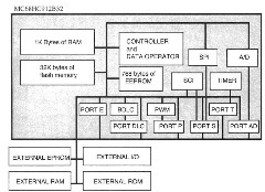
Figure 1.15. Expanded Wide Multiplexed Bus Mode of the MC68HC912B32
A significant advantage of the *A4 or ‘B32 is that either can be used in either the single-chip or either narrow or wide expanded multiplexed bus mode. The former mode is obviously useful when the resources within the microcontroller are enough for the application—that is, when there are enough memory and I/O devices for the application. The latter mode is required when more memory is needed, when a program is in an EPROM and has to be used with the ‘A4, or when more or different I/O devices are needed than are in the ‘A4.
MC68HC812A4 and MC68HC912B32 Organizations (Microcontrollers)
Next post: Summary and Further Reading (Microcontrollers)
Previous post: Variable Word Width (Microcontrollers)
