2.5
The next class of instructions, the control instructions, are those that affect the program counter PC. After the MOVE class, this class composes the most-often-used instructions. Control instructions are divided into conditional branching instructions and other control instructions. We discuss conditional branching first and then the others.
The bra instruction loads the PC with a new value, using relative addressing discussed in §3.3. It adds the last byte of its instruction, called the offset, to the PC. Branch statements have “long” branch counterparts where each mnemonic is prefaced with an L, such as lbra, and the offset is two bytes, enabling the programmer to add larger values to the PC, to branch to locations further from the instruction.
Table 2.8. Conditional Branch Instructions
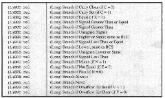
Conditional branch instructions test the condition code bits. As noted earlier, these bits have to be carefully watched, for they make a program look so correct that you want to believe that the hardware is at fault. The hardware is rarely at fault. The condition code bits are often the source of the fault because the programmer mistakes where they are set and which ones to test in a conditional branch. The instructions should now be reviewed with regard to how they affect the condition code bits. See the right columns of the CPU12RG/D manual Instruction Set Summary. Note that move instructions generally either change the N and Z bits or change no bits; arithmetic instructions generally change all bits; logic instructions change the N and Z bits; and edit instructions change all bits. However, there are many exceptions, and these exceptions are precisely the ones that cause mystifying errors. There is sound rationale for which bits are set and the way they are set. Some of that is discussed in this topic. But most of it is simply learned by experience. We conclude by reminding you that when your program does not work and you have checked every angle, carefully examine the setting and testing of the condition code bits. Now we look al the testing of these bits in detail.
Eight simple branching instructions test only a single condition code register bit: BNE, BEQ, BPL, BMI, BVC, BVS, BCC, and BCS. The letters S and C are used for “set” and “clear” (to 1 and 0, respectively) in branching instruction mnemonics.
Frequently, two numbers are compared, as in a compare instruction or a subtraction. One would like to make a branch based on whether the result is positive, negative, and so forth. Table 2.8 shows the test and the branching statement to make depending on whether the numbers are interpreted as signed numbers or unsigned numbers. The branch mnemonics for the two’s-complement numbers, or signed, numbers case are the ones usually described in mathematical “greater or less” prose. For example, BLT for “branch if less than.” BLE for “branch if less than or equal to,” and so forth. The mnemonics for unsigned numbers are described in mathematical “high or low” prose, offbeat enough to

Figure 2.16. Decision Tree
keep you from confusing them with the signed ones, for example, BLO for “branch if lower,” BLS for “branch if lower or the same,” BHI for “branch if higher,” and BHS for “branch if higher or the same.” Notice that BLO is the same instruction as BCS, and BHS is the same instruction as BCC. Here then is an example of two different mnemonics describing the same instruction, something that is sometimes warranted when the programmer will be using the same instruction with two distinct meanings.
Figure 2.16 illustrates a flow chart of several tests that form a decision tree. In Figure 2.17 and subsequent figures, labels are written left justified and end in a colon. Upon entry at label LO, location $801 is tested; if it is positive, go to L2 if location 802′s unsigned value is greater than $32, otherwise go to L3. If location $801 is negative, go to L4 if location $801 bit 2 is zero, otherwise go to L5. The program segment in Figure 2.17 implements this decision tree.
Do not be concerned about calculating the relative branch offsets; §3.3 will discuss this calculation. One should consult Table 2.8 for a while to make sure that the correct branch is being chosen. For example, to test a register value greater than or equal to a memory value, you might be tempted to use the simple branch BPL for signed numbers instead of BGE. The problem is that you want the branch test to work even when subtraction or comparison generates a signed overflow. But this is just exactiy when the
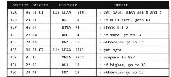
Figure 2.17. Program Segment for a Decison Tree
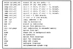
Table 2.9. Other Control Instructions
sign is incorrect; then using BPL cannot be used to replace BGE. Thus, after a compare or subtract between signed numbers, use BGE rather than BPL. You might also be tempted to use BPL for the unsigned test. However, if accumulator A has $80 and the immediate operand is $32, then N = 0 after performing the test. Thus BPL takes the branch, even though it should not because $32 is not higher than $80. Thus after an unsigned number comparison or subtraction, use BHS rather than BPL.
A rather amusing instruction, BRN L, which “branches never” regardless of the location L, is the opposite to the “branch always” instruction. It is useful because any branching instruction can be changed to a BRA or BRN instruction just by changing an opcode byte. This allows a programmer to choose manually whether a particular branch is taken while he or she is debugging a program.

Figure 2.18. Program Segment for Setting, Clearing, and Testing of a Bit
![]()
Figure 2.19. Program Segment for a Wait Loop
We now consider the control instructions other than conditional branches. See Table 2.9. Some instructions combine a logical or arithmetic test with a conditional branch and do not modify condition codes. BRCLR branches if all “1″ bits in the mask are “0″ in the word read from memory. Similarly, BRSET branches if all masks “3″ bits are “1″ in the word read from memory. These bits can be set and cleared using BSET and BCLR listed in Table 2.6. Figure 2.18 illustrates such setting, clearing, and testing of individual bits in memory. If this program segment is entered from location LI ($820), then bit 6 of location $802 is set there, and the instruction at L3 ($82A) branches to location L4 ($831). However, if this program segment is entered from location L2 ($826), then bit 6 of location $802 is cleared there, and the instruction at L3 ($82A) doesn’t branch but falls through to location $82F.
DBEQ, DBNE, IBEQ, and IBNE, which have a postbyte and a relative offset, decrement or increment a counter, which may be A, B, D, X, Y, or SP, and branch if the result in the counter is zero or nonzero, as indicated by the mnemonic and coded in the post byte. TBEQ and TBNE similarly test a register without incrementing or decrementing it and branch if the result is zero or nonzero. The low-order post byte bits indicate which register is used as a counter or test register (0, A; 1, B; 4, D; 5, X; 6, Y; and 7, SP) and the high-order three bits indicate the operation (000, DBEQ; 001, DBNE; 010, TBEQ; Oil, TBNE; 100, IBEQ; 101, IBNE). Post-byte bit 4 is appended as high bit to the instruction’s third byte to give a 9-bit offset.
The program segment in Figure 2.19 wastes time while an I/O operation takes place. (Calculation of the last byte, the offset $FD, will be discussed in §3.3.) The DBNE instruction takes three clock cycles, where each clock cycle is 125 nanoseconds. This instruction loops to itself five times in a delay loop, which wastes 1.875 /isec.
The simple jump instruction is the simplest control instruction; the effective address is put into the program counter. JMP $899 puts $899 into the program counter, and the next opcode byte is fetched from $899. It simply “jumps to location $899.”
You commonly encounter in programs a repeated program segment. Such a segment can be made into a subroutine so it can be stored just once but executed many times. Special instructions are used to branch to and return from such a subroutine. For example, if the subroutine begins at location $812, the instruction JSR $812 (for jump to subroutine) causes the PC to be loaded with $812 and the address immediately after the JSR instruction (say it is $807) to be pushed onto the hardware stack, low byte first. Figure 2.20a shows this return address, saved on the stack. BSR (for branch to subroutine) similarly pushes the program counter but locates the subroutine using relative addressing (§3.3). At the end of the subroutine, the 1-byte instruction RTS (for return from subroutine) pulls the top two bytes of the hardware stack into the PC, high byte first. JSR. SUB, and RTS, efficiently call, and return from, the subroutine.
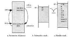
Figure 2.20. Subroutine and Handler Addresses
Figure 2.20 illustrates the use of the stack for holding temporary results as discussed in 2.1, with subroutine return addresses as illustrated in §2.5. We suggest that you step through this program using the simulator or debugger and watch the stack expand and compress. A constant in X, 1, is pushed on the stack before the subroutine and restored by pulling X after the subroutine is executed and has returned. This is commonly done when the calling routine needs the saved value later. The subroutine return address is saved on the stack by the BSR instruction and restored by the RTS instruction at the end of the subroutine. Inside the subroutine, the X and Y registers are saved and restored in order to exchange them. Pushing and pulling is often done to hold intermediary results.
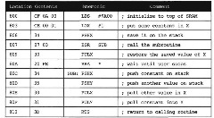
Figure 221. Program Segment for Swap Subroutine
A special call instruction permits saving and then loading a page register when saving and then loading the program counter. That extends the addressing capability, to over 16 bits in some 6812s, such as the ‘A4. The corresponding rtc instruction returns from a subroutine called by a call instruction.
As noted earlier, the stack pointer is to be initialized at the beginning of a program, with an instruction like lds #$C00. It must be initialized before any instruction, such as jsr or call, uses the stack pointer. If it is not, the rts or rtc does not work because the return address is “saved” in a location that is not RAM, so it is lost.
The (hardware or I/O) interrupt is very important to I/O interfacing. Basically, it is evoked when an I/O device needs service, either to move some more data into or out of the device or lo detect an error condition. Handling an interrupt stops the program that is running causes another program to be executed to service the interrupt and then resumes the main program exactly where it left off. The program that services the interrupt (called an interrupt handler or device handler) is very much like a subroutine, and an interrupt can be thought of as an I/O device tricking the computer into executing a subroutine. An ordinary subroutine called from an interrupt handler is called an interrupt service routine. However, a handler or an interrupt service routine should not disturb the current program in any way. The interrupted program should get the same result no matter if or when the interrupt occurs.
I/O devices may request an interrupt in any memory cycle. However, the data operator usually has bits and pieces of information scattered around in hidden registers. It is not prepared to stop the current instruction because it doesn’t know the values of these registers. Therefore, interrupts are always recognized at the end of the current instruction, when ail the data are organized into accumulators and other registers that can be safely saved and restored. The time from when an I/O device requests an interrupt until data that it wants moved is moved or the error condition is reported or fixed is called the latency time. Fast I/O devices require low latency interrupt service. The lowest latency that can be guaranteed must exceed the duration of the longest instruction because the I/O device could request an interrupt at the beginning of such an instruction’s execution.
The swi instruction is essentially like an interrupt. It saves all the registers as shown in Figure 2.20c and puts the contents of Sfff6, $fff7 into the program counter, lo begin an SWI handler at that address. All trap instructions (there are over 200 of them) save all the registers as the swi instruction does and put the contents of $fff8. SfflV into the program counter to begin a trap handler at that address. rti pulls the contents of the registers saved on the stack and fetches the next opcode at the address that is the returned program counter. wai stacks all the registers and waits for an interrupt to occur. stop stacks (he registers and stops all the 6812 clocks to conserve power. A system reset or an interrupt will cause the computer to resume after these instructions. Two interrupt inhibit bils (also called an interrupt mask bit) I and X are kept in the condition code; when they are set, interrupts are not permitted. A stop disable bit S is used to prevent execution of the stop instruction. bgnd places the MPU in a background mode to permit the background debug module to examine memory and registers and possibly modify some of them. If background debugging is not enabled, bgnd can be made lo act exactly like an swi instruction.
The condition code register, accumulators, program counter, and other registers in the controller and data operator are collectively called the machine state and are saved whenever an interrupt occurs as shown below, resulting in the stack in Figure 2.20c.
![]()
After completion of a handler entered by a hardware interrupt or similar instruction, the last instruction executed is return from interrupt (rti). All handlers end in an rti instruction. rti pulls the top nine words from the stack, replacing them in the registers the interrupt took them from. The rti instruction executes the operations:
![]()
You can modify the program in Figure 2.21 to see how the trap instruction saves and restores the machine state. Replace the BSR instruction at location $807 with an SWT instruction whose opcode is $3F (and a NOP, $A7) and the RTS instruction at location $810 with RTI whose opcode is $0B; put the adddress $80C into locations $FFF6 and $FFF7; and rerun this program. You should see that changing the registers inside the trap handler has no effect on the returned values of the registers, because they are saved on the stack and restored by the RTI instruction.
We have covered both the conditional and unconditional branch instructions. We have also covered the jump and related instructions together with subroutine branch and jump instructions. Control instructions provide the means to alter the pattern of fetching instructions and are the second most common type of instruction. If you use them wisely, they will considerably enhance the static and dynamic efficiency.
Control Instructions (Microcontrollers)
Next post: Special Instructions (Microcontrollers)
Previous post: Input-Output Instructions (Microcontrollers)
